
Method and system for reporting link state in a communication system

a communication system and link state technology, applied in the field of communication systems, can solve the problems of difficult to provide effective communication services, low flexibility in wireless network construction, and inability to realize the next-generation communication system including cells with a very small cell range, and achieve the effect of reducing the quantity of link state information

Inactive Publication Date: 2007-03-29
SAMSUNG ELECTRONICS CO LTD
View PDF6 Cites 84 Cited by
  • Summary
  • Abstract
  • Description
  • Claims
  • Application Information

AI Technical Summary

Benefits of technology

[0021] It is another aspect of the present invention to provide a method and system for link state report in order to select an optimum route, which can minimize the quantity of link state information in a communication system.

Problems solved by technology

However, it may be impossible to realize the next generation communication system including cells having a very small cell range, by using the current wireless network design scheme, which is for a centralized network.
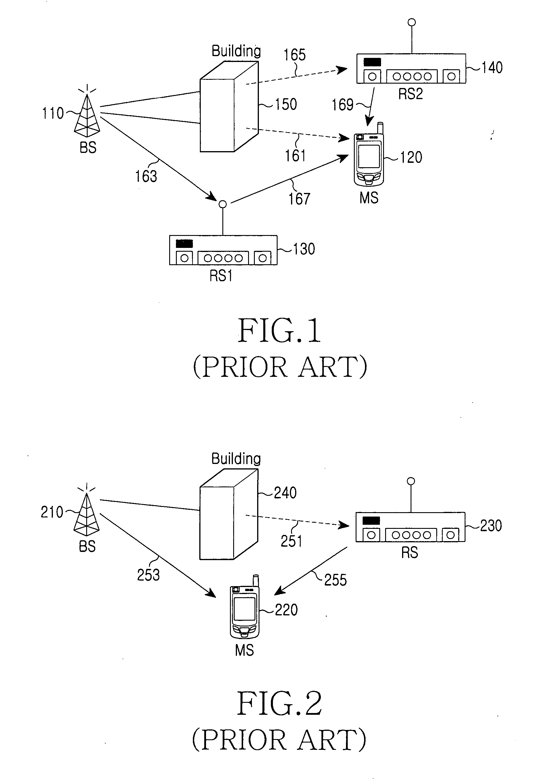
However, since the BS is fixed, there is a low flexibility in constructing the wireless network, and it is thus difficult to provide an effective communication service in a wireless environment which has a large change in the traffic distribution or required traffic quantity.
Therefore, the routing technique of the ad hoc network cannot be applied as it is to the cellular network using the multi-hop relay scheme.
Moreover, in a system using a Mobile Relay Station (MRS), the link states may change more severely.
However, there has yet to be proposed a routing technique which can select an optimum route while minimizing the quantity of message load in a cellular network using the multi-hop relay scheme.
Particularly, although the routing algorithm for the ad hoc network has been researched to a considerable degree, it is impossible to apply the routing technique of the ad hoc network, as it is, to the cellular network using the multi-hop relay scheme, as described above.
Such an unconditional report corresponds to transmission of unnecessary information from the MS 220 to the BS 210, which increases the load in the message transmission.

Method used


Image

  • Method and system for reporting link state in a communication system
  • Method and system for reporting link state in a communication system
  • Method and system for reporting link state in a communication system

Examples


Embodiment Construction

[0039] Hereinafter, preferred embodiments of the present invention will be described with reference to the accompanying drawings. In the following description, a detailed description of known functions and configurations incorporated herein will be omitted for the sake of clarity and conciseness.

[0040] According to the link state report method and system in a communication system of the present invention, at least one RS, which is located around an MS and provides a multi-hop relay route to the MS, reports information of the link state between the RS itself and the MS and the link state between the RS and a BS controlling the RS. Then, the MS recognizes the link state between the RS and the BS and the link state between the MS and the RS, selects an optimum link based on the recognized information, and reports the state information of the selected link to the BS. Further, the MS may select multiple reserved optimum routes having optimum link states and report them to the BS. Then, ...


PUM


Abstract

Disclosed is a method and system for link state report in order to select an optimum route in a wireless communication system which includes a mobile station, a base station for providing a service to the mobile station, and one or more relay stations for relaying information between the base station and the mobile station. The method includes: detecting a physical channel from the base station and measuring a link state of a link with the base station based on the detected physical channel, and inserting information of the measured link state into a message and broadcasting the message through a wireless channel.

Description

PRIORITY [0001] This application claims the benefit under 35 U.S.C. §119(a) of an application entitled “Method And System For Reporting Link State In A Communication System” filed in the Korean Industrial Property Office on Jun. 29, 2005 and assigned Ser. No. 2005-56903the contents of which are incorporated herein by reference. BACKGROUND OF THE INVENTION [0002] 1. Field of the Invention [0003] The present invention relates to a communication system, and more particularly to a method and a system for reporting a link state in a communication system using a multi-hop relay scheme. [0004] 2. Description of the Related Art [0005] Portable electronic devices, such as notebook computers, cellular phones, Personal Digital Assistants (PDAs) and Moving Picture Expert Group (MPEG) 3 (MP3) devices, are widely used in today's population. Most of such devices independently operate without inter-working with each other. In a wireless network constructed only by the portable electronic devices wi...

Claims


Application Information

Patent Timeline
Patent Type & Authority Applications(United States)
IPC IPC(8): H04Q7/20H04W4/06H04W24/00H04W40/12H04W40/18H04W88/04H04W92/10
CPCH04L5/0007H04L5/0032H04L5/005H04L5/0057H04L45/123H04W92/10H04W24/00H04W40/12H04W40/18H04W88/04H04W4/06H04B17/40
Inventor CHO, JAE-WEONKANG, HYUN-JEONGJOO, PAN-YUHSON, JUNG-JELIM, HYOUNG-KYULEE, SUNG-JINLEE, MI-HYUNSON, YEONG-MOONKIM, YOUNG-HO
Owner SAMSUNG ELECTRONICS CO LTD
Learn More