Integrated ultrasound imaging and ablation probe

Inactive Publication Date: 2007-03-29
GENERAL ELECTRIC CO
View PDF11 Cites 194 Cited by
  • Summary
  • Abstract
  • Description
  • Claims
  • Application Information

AI Technical Summary

Benefits of technology

[0009] Briefly, in accordance with aspects of the present technique, a system for imaging and providing therapy to one or more regions of interest is presented. The system includes an imaging and therapy catheter configured to image an anatomical region to facilitate assessing need for therapy in the one or more regions of interest within the anatomical region and delivering thera

Problems solved by technology

Heart rhythm problems or cardiac arrhythmias are a major cause of mortality and morbidity.
A drawback of these techniques however is that these procedures are extremely tedious requiring considerable manpower, time and expense.
Further, the long procedure times associated with the currently available catheter-based ablation techniques increase the risks associated with long term exposure to ionizing radiation to the patient as well as medical personnel.
Additionally, with RF ablation, the tip of the catheter is disadvantageously required to be in direct contact with each of the regions of the anatomy to be ablated.
However, fluoroscopic techniques disadvantageously suffer from drawbacks, such as difficulty in visualizing soft tissues, which may result in a less precise definition of a therapy pathway.
Consequently, these RF ablation techniques typically result in greater collateral damage to tissue surrounding the ablation sit

Method used


Image

  • Integrated ultrasound imaging and ablation probe
  • Integrated ultrasound imaging and ablation probe
  • Integrated ultrasound imaging and ablation probe

Examples


exemplary embodiment 38

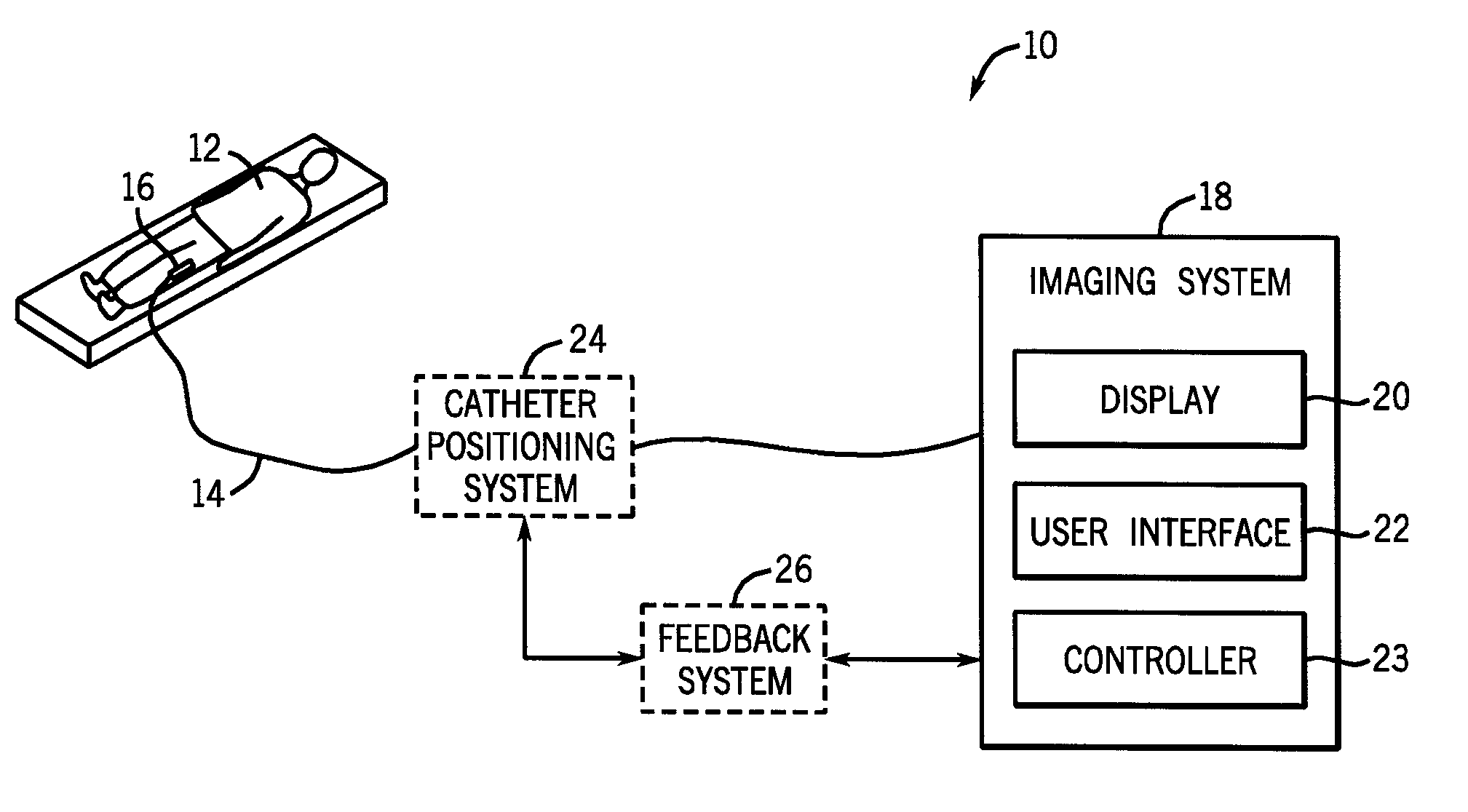
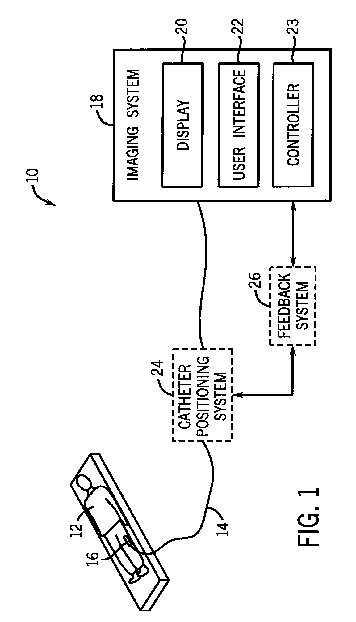
[0046]FIG. 3 is an illustration of an exemplary embodiment 38 of an imaging and therapy catheter 40 for use in the system 10 illustrated in FIG. 1. Further, in FIG. 3, the imaging and therapy catheter 40 is illustrated as having an imaging and therapy transducer 42. As previously noted, the imaging and therapy catheter 40 may include an imaging and therapy transducer having integrated or separate imaging and therapy components. The embodiment of the imaging and therapy catheter 40 illustrated in FIG. 3 is shown as having an integrated imaging and therapy transducer 42 having integrated imaging and therapy components. In one embodiment, the illustrated integrated imaging and therapy catheter 40 may be configured to facilitate real-time three-dimensional imaging of an anatomical region as well as deliver therapy to one or more regions in the anatomical region. For example, in the case of an integrated ultrasound imaging and therapy catheter, a real-time, three-dimensional ultrasound i...

exemplary embodiment 52

[0048] Referring now to FIG. 4, an exemplary embodiment 52 of an imaging and therapy catheter 54 having a large field of view is illustrated. The large field of view may encompass 360 degrees, in one embodiment. As depicted in FIG. 4, the imaging and therapy catheter 54 is illustrated as having an imaging and therapy transducer 56. In certain embodiments, the imaging and therapy catheter 54 may include a single imaging and therapy transducer having a large field of view. Alternatively, in other embodiments, a plurality of imaging and therapy transducers may be used in the imaging and therapy catheter 54. Further, reference numeral 58 is representative of a real-time three-dimensional imaged volume. In the illustrated embodiment, the real-time three-dimensional imaged volume 58 is shown as having a cylindrical volume. The imaging beam is mechanically and / or electronically scanned throughout the imaged volume 58. In a presently contemplated configuration, reference numeral 60 is repre...


PUM


Abstract

A system for imaging and providing therapy to one or more regions of interest is presented. The system includes an imaging and therapy catheter configured to image an anatomical region to facilitate assessing need for therapy in one or more regions within the anatomical region and delivering therapy to the one or more regions of interest within the anatomical region. In addition, the system includes a medical imaging system operationally coupled to the catheter and having a display area and a user interface area, wherein the medical imaging system is configured to facilitate defining a therapy pathway to facilitate delivering therapy to the one or more regions of interest.

Description

CROSS-REFERENCE TO RELATED APPLICATIONS [0001] The present invention is a continuation-in-part of U.S. Ser. No. 11 / 225,331 filed Sep. 13, 2005, and claims the benefit of provisional application U.S. Ser. No. 60 / 739,799, filed Nov. 23, 2005.BACKGROUND OF THE INVENTION [0002] The invention relates generally to diagnostic imaging, and more particularly to an integrated ultrasound imaging and ablation probe. [0003] Heart rhythm problems or cardiac arrhythmias are a major cause of mortality and morbidity. Atrial fibrillation is one of the most common sustained cardiac arrhythmias encountered in clinical practice. Cardiac electrophysiology has evolved into a clinical tool to diagnose and treat these cardiac arrhythmias. As will be appreciated, during electrophysiological studies, multipolar catheters are positioned inside the anatomy, such as the heart, and electrical recordings are made from the different chambers of the heart. Further, catheter-based ablation therapies have been employe...

Claims


Application Information

Patent Timeline
IPC IPC(8): A61B5/05
CPCA61B5/042A61B8/445A61B8/0883A61B8/12A61B8/4254A61B8/4472A61B8/4483A61B8/4488A61B8/463A61B8/483A61B8/485A61B17/2202A61B17/2256A61N7/022G01S15/8925G01S15/895G01S15/899G01S15/8918A61B2019/5278A61B8/08A61B2090/3782A61B5/283
Inventor LEE, WARRENSEYED-BOLORFOROSH, MIRSAIDWILDES, DOUGLAS GLENN
Owner GENERAL ELECTRIC CO
Why Eureka
Try Eureka