Catheter for diagnostic imaging and therapeutic procedures

a catheter and diagnostic imaging technology, applied in the field of catheters, can solve problems such as numbness, tingling or decreased sensation, and achieve the effect of preventing both recoil and whipping and reducing the opening siz

Inactive Publication Date: 2007-03-29
MEDRAD INC.
View PDF99 Cites 88 Cited by
  • Summary
  • Abstract
  • Description
  • Claims
  • Application Information

AI Technical Summary

Benefits of technology

[0024] In one presently preferred embodiment, the invention provides a catheter assembly for introducing fluid into a vessel. The catheter assembly includes a shaft, a hub affixed to a proximal end of the shaft, a stem affixed to a distal end of the shaft, and a tip affixed to the distal end of the stem. The stem has a porous section approximate a distal end thereof. The porous section defines a plurality of microholes generally distributed uniformly thereabout and inclined by a predetermined angle in a proximal direction. The tip includes a conically-shaped valve with an apex thereof pointing in the proximal direction and defining an opening thereat. As the fluid flows within the catheter assembly and pressure increases within the tip, the conically-shaped valve tends to flatten out distally thereby generally decreasing a size of the opening so that the amount of the fluid flowing out of the opening of the tip decreases and that out of the microholes of the stem increases. The forces of the fluid flowing out of the microholes and the opening substantially balance thereby enabling the position of the tip and stem within the vessel to remain stable while fluid is finely dispersed therefrom.
[0025] In a related embodiment, the invention provides a catheter assembly for introducing fluid into a vessel. The catheter assembly includes a stem and a tip affixed to a distal end of the stem. The stem has approximate its distal end a porous section. The porous section defines a plurality of microholes distributed thereabout, which are inclined by a predetermined angle in a proximal direction. The tip includes a conically-shaped valve with an apex thereof pointed in the proximal direction. The apex defines an opening whose size generally decreases as the conically-shaped valve flattens out distally as pressure of the fluid within the tip increases. The forces of the fluid flowing from within the catheter assembly out of the opening of the tip and out of the microholes of the stem substantially balance thereby preventing both recoil and whipping of the catheter assembly thus enabling the position thereof within the vessel to remain stable while the fluid is finely dispersed therefrom.
[0027] In related embodiment, the invention provides a catheter assembly for introducing fluid into a vessel. The catheter assembly includes a stem and a restrictor affixed to a distal end of the stem. The stem has approximate its distal end a porous section. The porous section defines a plurality of microholes distributed thereabout, which are inclined by a predetermined angle in a proximal direction. The restrictor defines an opening therein whose size generally decreases as pressure of the fluid within the restrictor increases. The forces of the fluid flowing from within the catheter assembly out of the opening of the restrictor and out of the microholes of the stem substantially balance to prevent axial and radial movement of the catheter assembly thus enabling a position thereof within the vessel to remain stable while the fluid is finely dispersed therefrom in a cloud-like form.

Problems solved by technology

Depending on the duration of the interruption and the part of the brain affected, a stroke can cause symptoms such as numbness, tingling or decreased sensation; vision problems; vertigo; difficulty in reading; inability to speak or to understand speech; loss of balance; paralysis of an arm, leg, side of the face, or other body part; loss of consciousness; and even death.
Smaller incisions inflict less trauma upon patients, and thus require less labor to close and less time to heal as well as result in shorter hospital stays.
As a result of this requirement, smaller diameter catheters pose certain disadvantages, namely the problems of “recoil” and “whipping.” These shortcomings are found not only in catheters in which the opening in the distal tip is the sole exit for the fluid, but also in catheters that have sideholes in the wall of the distal portion of the stem whether or not they have an opening in the distal end.
More specifically, certain catheter designs are known to give rise to fluidic forces that can cause the tip of the catheter to move as a result of the high velocity at which the fluid is ejected from the distal end.
Much of the fluid will then miss the targeted artery and flow elsewhere downstream, resulting in wasted contrast fluid and unnecessary expense.
Even more ominously, the high velocity of the misdirected fluid—and any whipping of the tip itself—can cause dissection of the vessel walls and dislodgement of plaque that may have accumulated there.
If the sideholes are not uniformly spaced about the circumference of the catheter, then the tip of the catheter will have a tendency to whip.
Moreover, flow through the sideholes alone will not be sufficient to prevent recoil of a catheter during an injection.
Another problem with various prior art catheters involves streaming effects.
This is the tendency of the contrast fluid upon exit from the tip of the catheter to remain concentrated, i.e., the fluid will not be widely and finely dispersed within the targeted area When this occurs, the targeted vessel has not received optimal opacification (i.e., rendering the targeted vessel readily discernable via imaging equipment) and thus the flow of fluid therethrough cannot be well observed during the imaging procedure.
Regardless of how well the Spiroff design balances the radial and axial forces of injection / infusion, it still permits fluid to flow at high velocity out of the opening in the distal end of the catheter, which creates the potential for dissection of tissue and dislodgement of plaque from the vessel walls.
Although these valves allow passage of a guidewire, they do not permit measurement of the pressure within the vessel through the catheter.
This catheter thus poses a comparatively high risk of dissection of tissue and dislodgement of plaque from the vessel walls.
Together, the balanced fluidic forces taught by Spiroff and the variable opening taught by Person et al. appear to present the catheter, and the concomitant disadvantages, of the '679 patent.

Method used


Image

  • Catheter for diagnostic imaging and therapeutic procedures
  • Catheter for diagnostic imaging and therapeutic procedures
  • Catheter for diagnostic imaging and therapeutic procedures

Examples


first embodiment

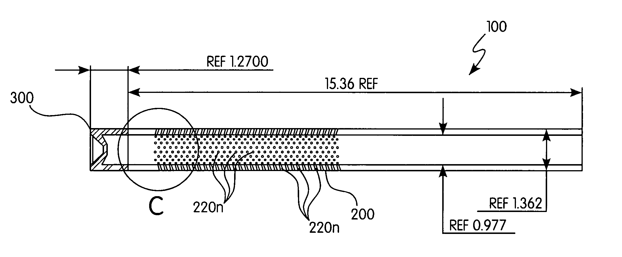
[0068]FIGS. 4A-4R illustrate the invention along with various preferred and alternative aspects. The catheter, generally designated 100, includes a stem equipped with a porous section 200 and a restrictor 300 affixed to the distal end of the stem. As shown in FIG. 4B, the stem is approximately 15.36 mm in length for catheter 100 made in a 4 French size, with approximate outer and inner (lumen) diameters of 1.362 mm and 0.977 mm, respectively. For catheter 100 in the 5 French size shown in FIG. 4G, the stem has a length of approximately 15.9 mm, with approximate outer and inner diameters of 1.694 mm and 1.21 mm.

[0069] Preferably located in proximity to the distal end of the stem, the porous section 200 includes a large plurality of microholes 220n, each of which in communication with the lumen of the catheter 100. For reasons explained in more detail below, all microholes 220n in the porous section 200 are preferably made having the same diameter. Although the diameter is generally b...

second embodiment

[0089]FIGS. 5A-5B illustrate a catheter, generally designated 110, according to the invention. This catheter includes a stem equipped with a porous section 200 along with a restrictor 400 affixed to the distal end of the stem.

[0090] Like the previous embodiment, the porous section 200 includes a large plurality of microholes 220n, each of which in communication with the lumen of the catheter. Although generally set between approximately 5 to 125 microns, the preferred diameter for the microholes 220n is about 50 microns, with all microholes 220n preferably having the same diameter. As best shown in FIG. 5B, the microholes are angled in the proximal direction. The degree of angularity can range approximately from 0 to 45 degrees, with a preferred angle of 20 degrees, though the exact angle will depend on the factors noted above. The preferred length of porous section 200 is 6 mm, though it can range from 2 mm to 2 cm or even longer. The microhole pattern is preferably located close t...

third embodiment

[0096]FIGS. 6A-6C illustrate a catheter, generally designated 120, according to the invention. This catheter includes a stem along with a restrictor 500 affixed to the distal end of the stem. Catheter 120 is similar to the other disclosed embodiments in that it uses a combination of proximally-angled microholes and a restrictor to create a uniform, fog-like dispersion of fluid during an injection while the tip remains stationary in the vessel or other structure into which it has been placed.

[0097] Like the previous embodiments, the stem has a porous section 200 that features a large plurality of microholes 220n, each of which in communication with the lumen of the catheter. Unlike those embodiments, however, the microholes of catheter 120 are situated not only in the stem but also in the restrictor 500. The microholes of restrictor 500 are generally designated in the drawings as 520n.

[0098] The microholes 220n of the stem have a diameter generally set between approximately 5 to at ...


PUM


Abstract

A catheter for use in introducing fluid into a vessel or other bodily structure. The catheter comprises a stem and a restrictor. The stem has approximate a distal end thereof a porous section that defines microholes distributed thereabout, which are inclined by a predetermined angle in the proximal direction. Affixed to the stem, the restrictor includes a conically-shaped valve with an apex thereof defining an opening and pointing in the proximal direction. The opening generally decreases in size as the conically-shaped valve flattens out distally as the pressure of the fluid within the tip increases. The forces of the fluid flowing out of the opening of the restrictor and out of the microholes of the stem substantially balance thereby substantially eliminating both recoil and whipping of the catheter, thus enabling its position to remain exceptionally stable while the fluid is finely dispersed therefrom in a cloud-like form.

Description

CROSS-REFERENCE TO RELATED APPLICATION [0001] This application claims the benefit of U.S. Provisional Application No. 60 / 520,071, filed 15 Nov. 2003, which is incorporated herein by reference.FIELD OF THE INVENTION [0002] The invention relates generally to catheters used for diagnostic imaging, therapeutic treatments, drug delivery, perfusion, and various other interventional procedures that require delivery of fluids into the vasculature or other structures of a patient. More particularly, the invention pertains to a catheter having an innovative distal end whose position remains exceptionally stable within the vasculature or other structure while the fluid is very finely dispersed therefrom during such procedures. BRIEF DESCRIPTION OF RELATED ART [0003] The following information is provided to assist the reader to understand the invention disclosed below and at least some of the many applications in which it will typically be used. It is also provided to inform the reader of at le...

Claims


Application Information

Patent Timeline
Patent Type & Authority Applications(United States)
IPC IPC(8): A61M25/16A61M25/18A61MA61M25/00
CPCA61M25/0041A61M25/0043A61M25/0068A61M25/0069A61M25/007A61M2025/0076A61M25/008A61M25/01A61M2025/0057A61M2025/0073A61M25/0074
Inventor BRUCKER, GREGORY G.SAVAGE, STEVEN D.GARDNER, JOHN R.TROMBLEY, III, FREDERICK W.
Owner MEDRAD INC.
Why Eureka
Try Eureka