Method and apparatus for pumping blood

a technology of blood pump and blood flow, applied in the direction of positive displacement pump, prosthesis, liquid engine, etc., can solve the problems of reducing the efficiency of oxygenation under certain physiologic circumstances, preventing wide-spread use, and reducing the efficiency of oxygenation under certain circumstances, so as to increase the speed of the second blood pump and increase the speed of the first blood pump

Active Publication Date: 2007-03-29
ABIOMED
View PDF34 Cites 82 Cited by
  • Summary
  • Abstract
  • Description
  • Claims
  • Application Information

AI Technical Summary

Benefits of technology

[0021] The method may further include increasing the speed of the second blood pump until a drop in the second blood flow is detected, and increasing a speed of the first blood pump until a drop in the first blood flow is detected. In the method, determining the first blood flow may include dithering at least one of speed and power usage of the first pump and determining the second blood flow may include dithering at least one of speed and power usage of the second pump.

Problems solved by technology

While the use of the shunt may help to compensate for the imbalance, this scheme allows mixing of oxygenated blood with deoxygenated blood reducing the efficiency of oxygenation under certain physiologic circumstances.
While positive displacement pumps have been successful in mimicking the functions of the human heart, a number of difficulties associated with the use of these devices has prevented wide spread use.
For example, positive displacement pumps currently in use tend to be too large in size to be used in patients with smaller thoracic cavities.
In addition, an energy converter is typically used to drive the hydraulic fluid between the left and right chambers, thereby increasing the overall size of the device.
Moreover, positive displacement pumps typically require the use of artificial valves in order to pump blood from the pumping chambers in a unidirectional manner.

Method used


Image

  • Method and apparatus for pumping blood
  • Method and apparatus for pumping blood
  • Method and apparatus for pumping blood

Examples


Embodiment Construction

[0033] This invention is not limited in its application to the details of construction and the arrangement of components set forth in the following description or illustrated in the drawings. The invention is capable of other embodiments and of being practiced or of being carried out in various ways. Also, the phraseology and terminology used herein is for the purpose of description and should not be regarded as limiting. The use of “including,”“comprising,” or “having,”“containing”, “involving”, and variations thereof herein, is meant to encompass the items listed thereafter and equivalents thereof as well as additional items.

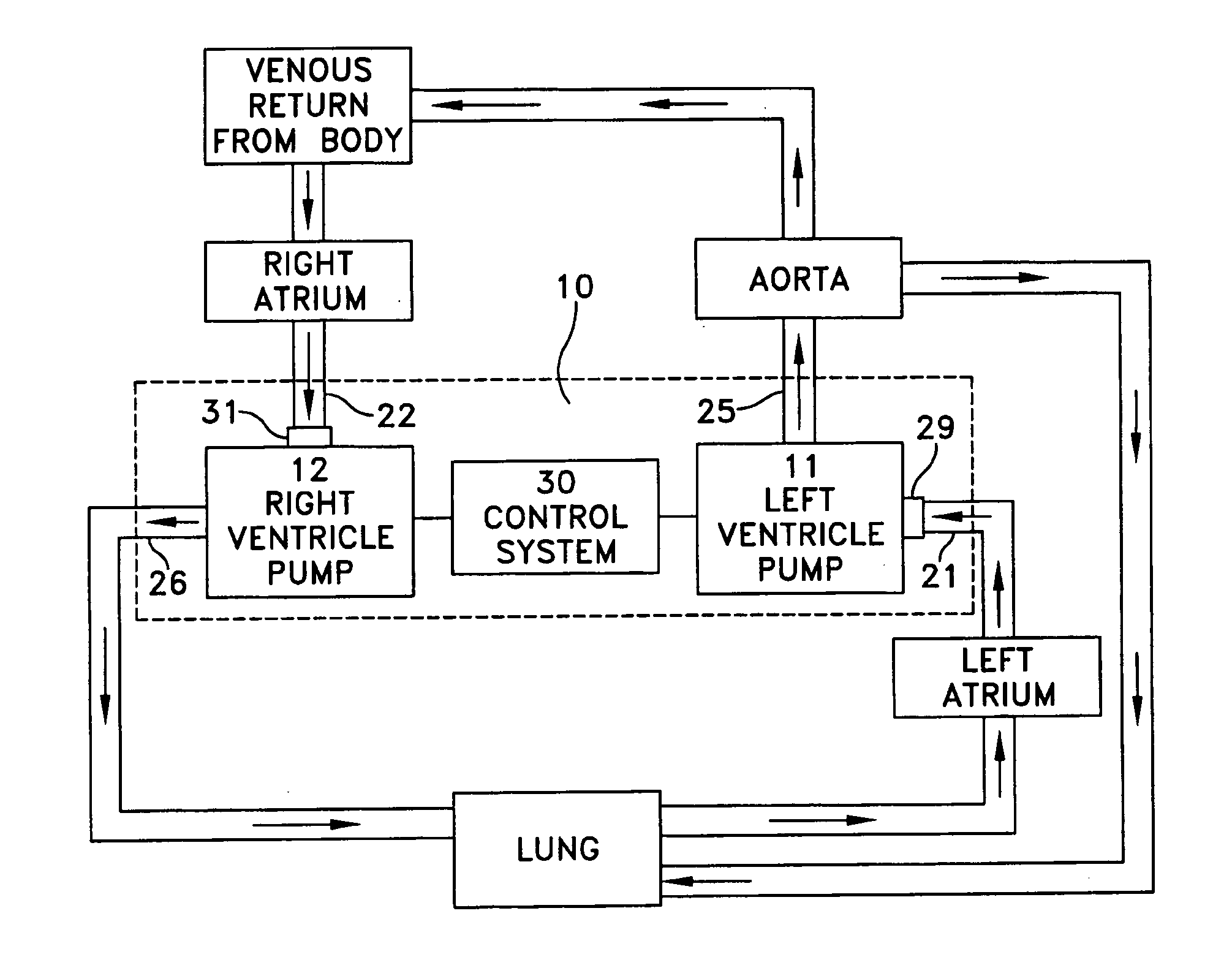
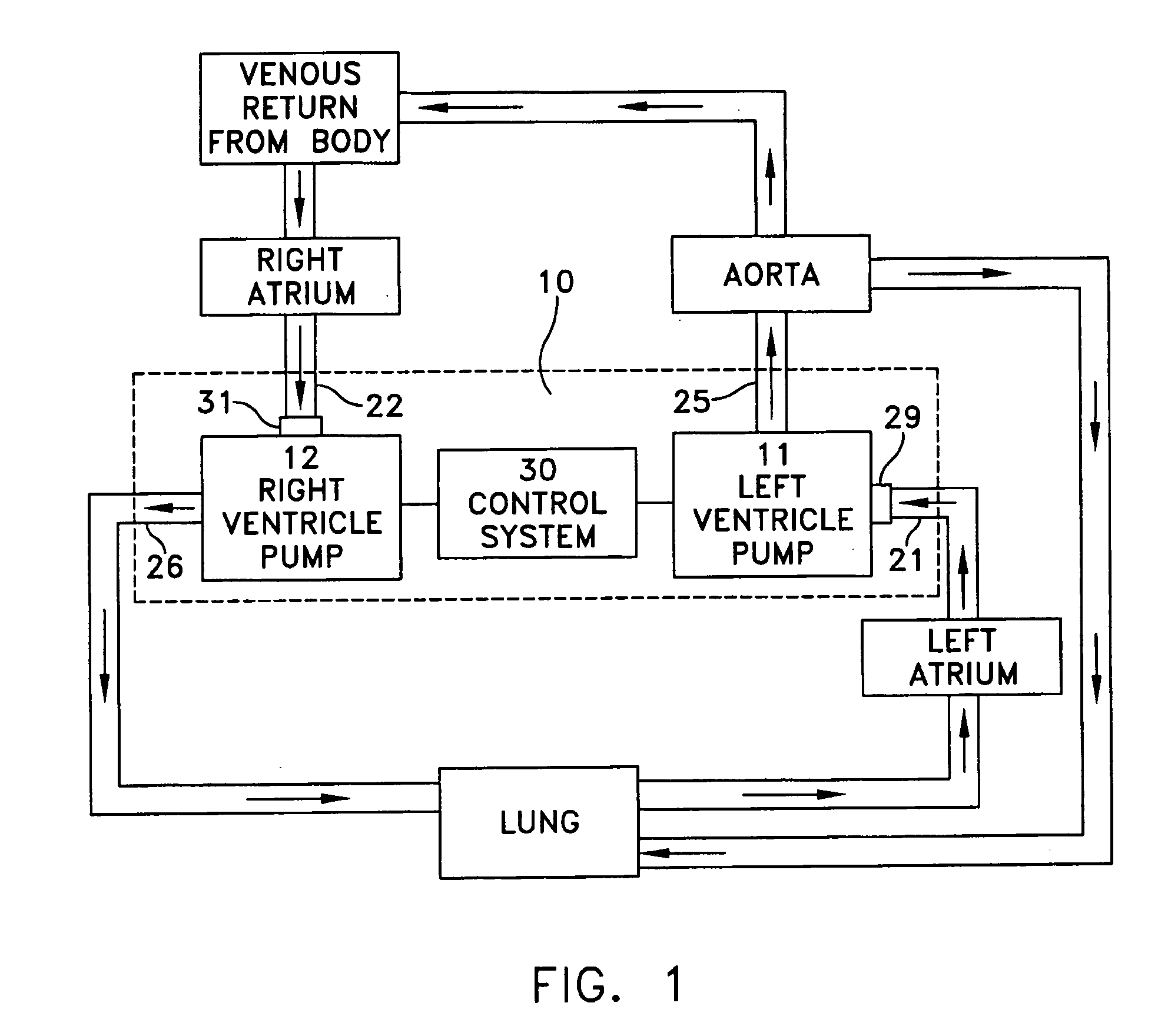
[0034] As described below, at least some embodiments of the present invention are directed to a totally artificial heart and methods of controlling artificial hearts. Nonetheless, at least some embodiments of the invention or particular aspects of embodiments of the invention may be used with other devices, such as ventricular assist devices (VADs) and with e...


PUM


Abstract

At least one aspect is directed to a totally artificial heart, and at least another aspect is directed to a method of controlling blood flow in a patient. The totally artificial heart may include a first rotary pump having an input to receive blood and an output to provide blood to a patient's lungs, a second rotary pump having an input to receive blood and an output to provide blood to the patient's body, a first sensor associated with the first rotary pump, a second sensor associated with the second rotary pump, and a control system coupled to the first sensor, the second sensor, the first rotary pump and the second rotary pump and configured to control characteristics of the first rotary pump and the second rotary pump based on signals received from at least one of the first sensor and the second sensor such that an average flow of blood through the second rotary pump is greater than an average flow of blood through the first rotary pump

Description

BACKGROUND OF INVENTION [0001] 1. Field of Invention [0002] Embodiments of the invention relate generally to, but are not limited to, systems and methods for pumping blood through the body, and more particularly, at least one embodiment is directed to a totally artificial heart and method of controlling the artificial heart, while other embodiments may be directed to devices and methods for assisting the operation of a patient's heart. [0003] 2. Discussion of Related Art [0004] Total artificial hearts (TAH) utilizing positive displacement pumps have been successfully used to replace the functions of the human heart. See, for example, U.S. Pat. No. 4,888,011 to Kung et al. entitled “Artificial Heart” (incorporated herein by reference in its entirety). Such pumps utilize an alternating left-right pumping device with left and right pumping chambers, each including a membrane or diaphragm separating the chamber into a blood flow section and a hydraulic section. During left-side blood pu...

Claims


Application Information

Patent Timeline
Patent Type & Authority Applications(United States)
IPC IPC(8): A61M1/12F04B49/00
CPCA61M1/101A61M1/1086A61M2205/702A61M2205/3331A61M1/12A61M2205/3334A61M60/148A61M60/546A61M60/554A61M60/232A61M60/237A61M60/562A61M60/196
Inventor KUNG, ROBERT T.V.ZARINETCHI, FARHADHART, ROBERT M.
Owner ABIOMED
Why Eureka
Try Eureka