Engine system arrangement with on-board ammonia production and exhaust after treatment system

a technology of exhaust treatment and engine system, which is applied in the direction of engines, machines/engines, mechanical equipment, etc., can solve the problems of unsatisfactory emissions of particulate matter and nox, the inability to develop a fossil fuel combustion strategy that completely avoids the production of undesirable emissions, and the inability to achieve aftertreatmen

Inactive Publication Date: 2007-04-05
CATERPILLAR INC
View PDF11 Cites 13 Cited by
  • Summary
  • Abstract
  • Description
  • Claims
  • Application Information

AI Technical Summary

Problems solved by technology

Among these undesirable emissions are particulate matter and NOx.
Although there has been much progress in developing methods of operating internal combustion engines in ways that reduce undesirable emissions, it may be impossible to develop a fossil fuel combustion strategy that completely avoids the production of undesirable emissions.
Therefore, much effort has been directed to aftertreatment strategies that remove or change undesirable emissions into more acceptable chemical compounds before the exhaust is vented to atmosphere.
While these systems can be somewhat effective, they are problematic in that they require an external urea tank that must be periodically refilled.
While this strategy can be quite effective, such traps often require periodic regeneration by burning to oxidize the particles.
These control systems can fail, and even if they do not fail, these particle traps cyclically apply increased back pressure on the engine which decreases efficiency to some measurable extent.
In some instances, particularly at prolonged low load conditions, there may not be enough heat generated by the engine to regenerate the particle trap without some auxiliary heat source or by temporarily increasing engine output for the sole purpose of particle trap regeneration.

Method used


Image

  • Engine system arrangement with on-board ammonia production and exhaust after treatment system
  • Engine system arrangement with on-board ammonia production and exhaust after treatment system
  • Engine system arrangement with on-board ammonia production and exhaust after treatment system

Examples


Embodiment Construction

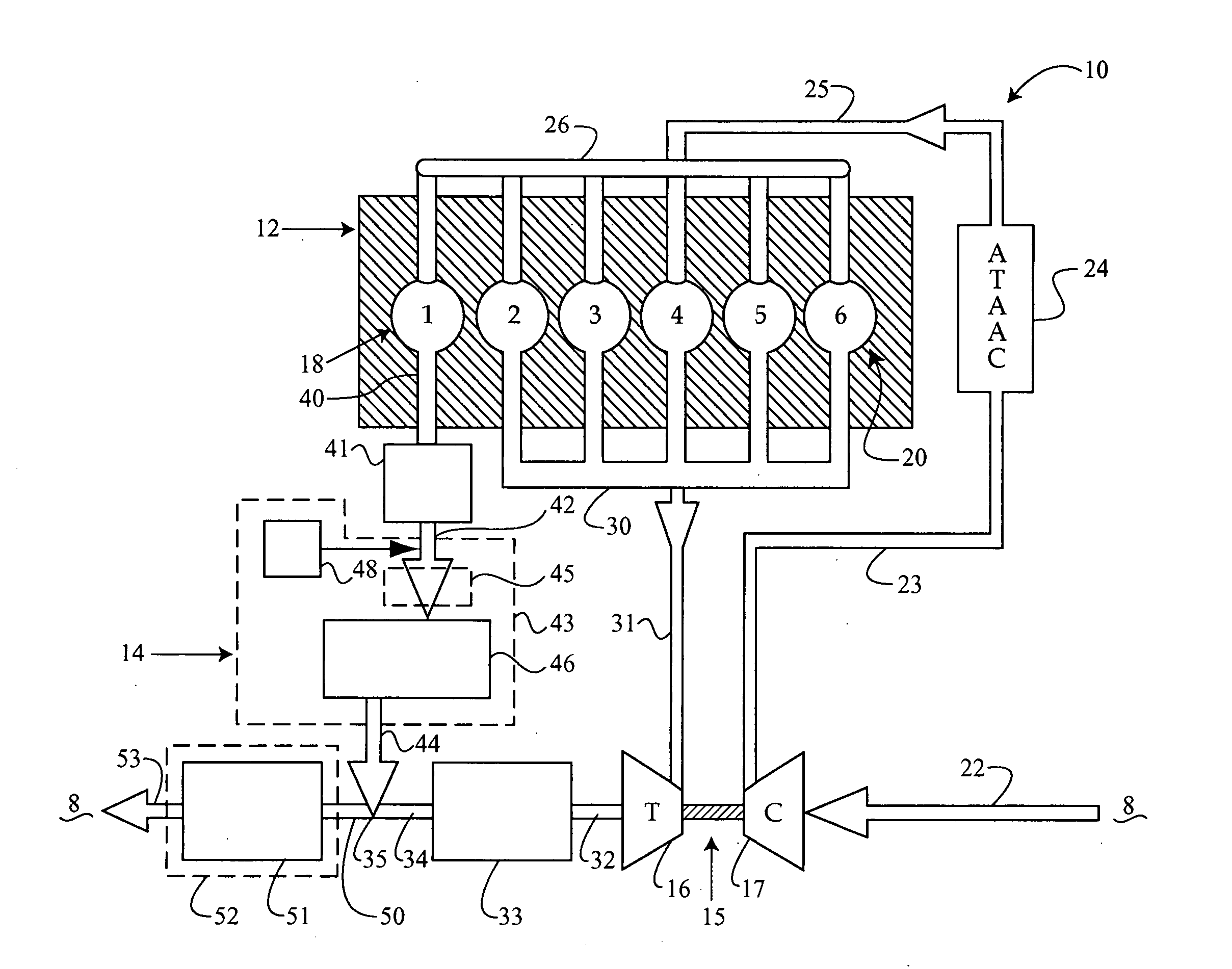
[0012] Referring to FIG. 1, an engine system 10 includes an air intake 22 that receives air from atmosphere 8 and vents exhaust back to atmosphere 8 via a tailpipe 53. Engine system 10 includes a first combustion chamber group 18 and a second combustion group 20. In the illustrated example, the first and second combustion chamber groups 18, 20 are part of a single engine 12. However, those skilled in the art will appreciate that engine system 10 could include two or more separate engines where the first and second combustion chamber groups are located in the respective engines. In the illustrated example, the second combustion chamber group 20 is primarily responsible for producing the bulk of the power output of the engine, and the first combustion group 18 is generally responsible for creating excessive NOx for conversion to ammonia. The ammonia is later reacted with NOx produced by the second combustion group 20 to produce nitrogen and water that is vented to atmosphere 8 via tai...


PUM


Abstract

An engine system includes first and second combustion chamber groups that supply exhaust to respective first and second exhaust passages. NOx in the exhaust of the first combustion group is converted to ammonia, such as by enriching the exhaust with fuel and then passing the mixture over an appropriate catalyst. Particles are trapped and continuously oxidized through appropriate placement of one or more particle traps coated with an appropriate oxidizing catalyst. NOx in the second passage from the second combustion group is combined with ammonia produced in the first passage and converted to nitrogen and water in a merged passage before being vented to atmosphere. This conversion is accomplished by passing the merged exhaust over an appropriate selective catalytic reduction catalyst.

Description

TECHNICAL FIELD [0001] The present disclosure relates generally to engine systems with after treatment systems to reduce undesirable emissions, and more particularly to an exhaust after treatment system with the ability to reduce particulate and NOx emissions, at least in part via a catalized reaction with a reductant. BACKGROUND [0002] Increasingly stringent emissions requirements are constantly pressuring researchers to perfect existing ways, and devise new ways, to reduce undesirable emissions. Among these undesirable emissions are particulate matter and NOx. Although there has been much progress in developing methods of operating internal combustion engines in ways that reduce undesirable emissions, it may be impossible to develop a fossil fuel combustion strategy that completely avoids the production of undesirable emissions. Therefore, much effort has been directed to aftertreatment strategies that remove or change undesirable emissions into more acceptable chemical compounds ...

Claims


Application Information

Patent Timeline
Patent Type & Authority Applications(United States)
IPC IPC(8): F01N3/00F01N3/10
CPCF01N3/0821F01N3/2066F01N2250/02F01N2610/02Y02T10/24Y02T10/12
Inventor DRISCOLL, JOSHROBEL, WADE J.
Owner CATERPILLAR INC
Why Eureka
Try Eureka