
Inspection scaffold of large component for boiler and building method thereof

a technology of inspection scaffold and boiler, which is applied in the direction of building scaffold, boiler supporting/setting arrangements, lighting and heating apparatus, etc., can solve the problems of difficult scaffold assembling, extremely long time required for assembling, and very difficult scaffold assembling work, so as to prevent a risk of a crash, reduce the time of scaffold assembling, and enhance the safety of work

Inactive Publication Date: 2007-04-05
HITACHI LTD
View PDF24 Cites 11 Cited by
  • Summary
  • Abstract
  • Description
  • Claims
  • Application Information

AI Technical Summary

Benefits of technology

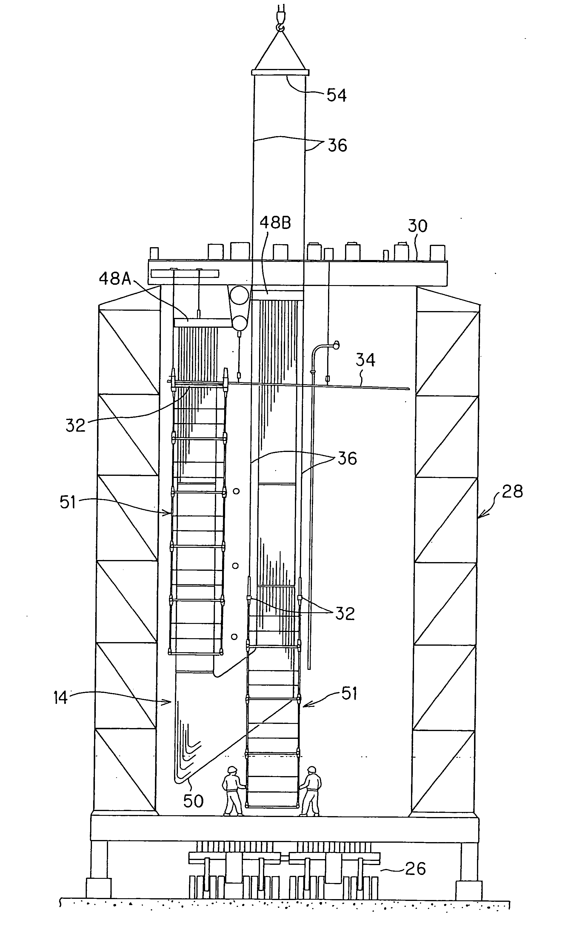
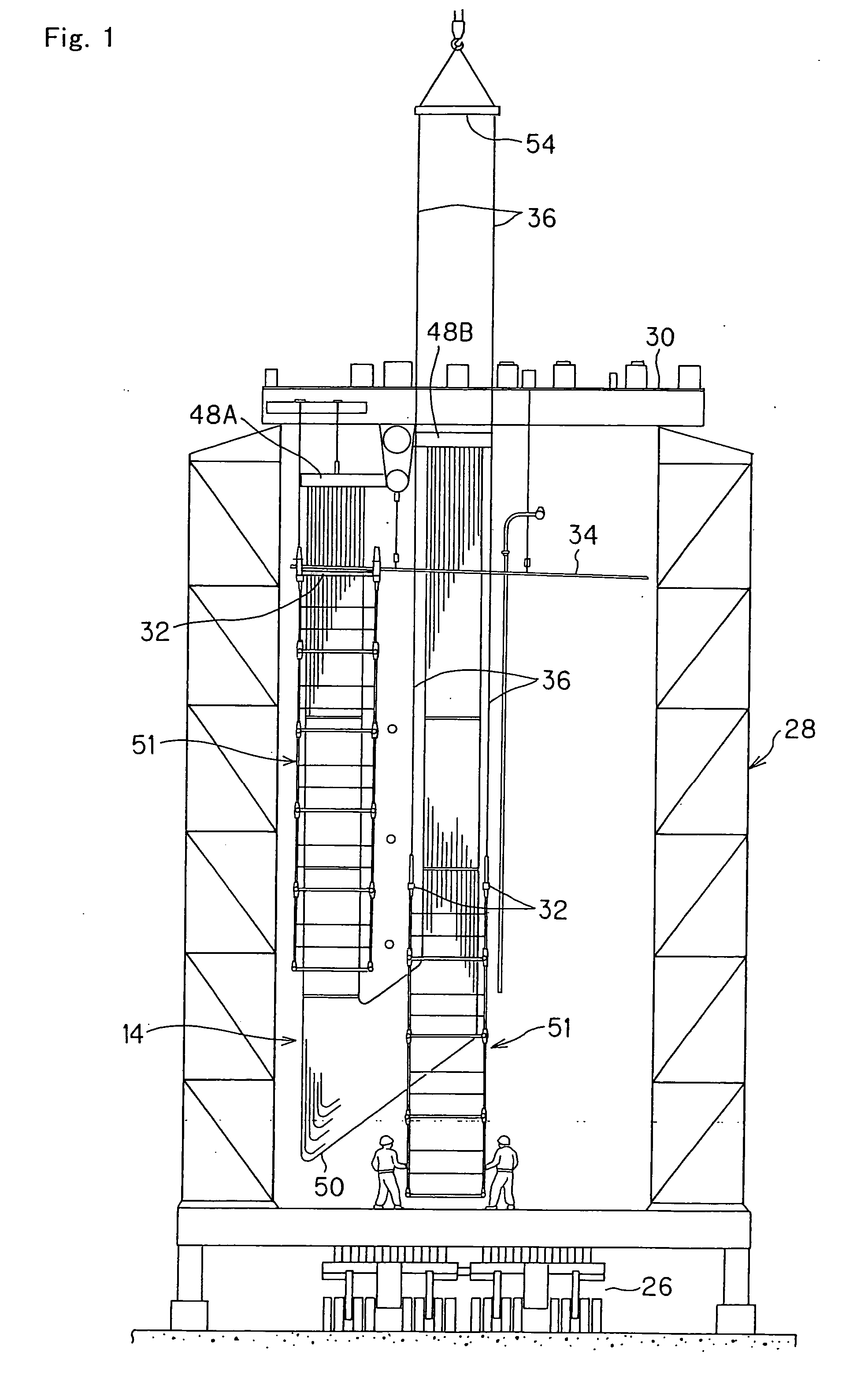
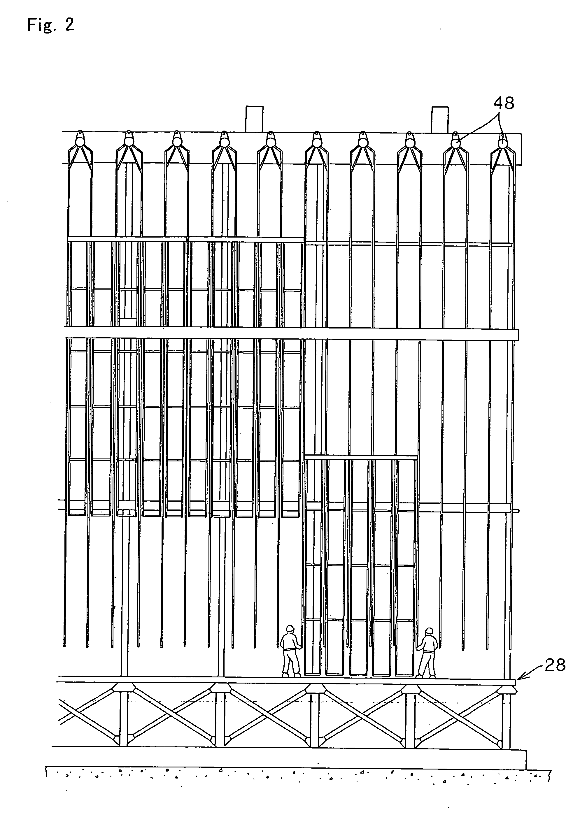
The present invention provides an inspection scaffold and a building method for safely assembling the scaffold to a large component, such as a boiler, without the need for high-place work. The scaffold is assembled by raising each scaffold unit composed of scaffold lifting / supporting beams, rods, and scaffold boards, and coupling them with the horizontal member of the large component. The scaffold is then integrated with the large component and suspended and supported by it. This method significantly reduces the time required for scaffold assembly and increases safety. The scaffold is also designed to prevent a risk of a crash caused by the rolling of the suspended structure of the large component.

Problems solved by technology

Consequently, components other than the coil being an inspection object are existing around the coil, and therefore, there is a problem that the assembling work of the scaffold is very difficult.
In particular, in the superheater, a lot of narrow coils are coupled to headers, this is vertically disposed in a structure well-ordered in a plane state, and equipped in a lot of lines with narrow intervals, and therefore, there are also problems that the work for the scaffold assembling is difficult and the time required for the assembling is extremely long.

Method used


Image

  • Inspection scaffold of large component for boiler and building method thereof
  • Inspection scaffold of large component for boiler and building method thereof
  • Inspection scaffold of large component for boiler and building method thereof

Examples


Embodiment Construction

[0028] Hereinafter, an optimal embodiment of an inspection scaffold of a large component for a boiler and a building method thereof according to the present invention is described with reference to the drawings.

[0029] At first, in FIG. 11, an internal sectional view of a boiler furnace 10 is shown. A second superheater 12 and a third superheater 14 are provided side by side at an upper position of the boiler furnace 10 having dozens of meters height. These are pendant coils suspended and supported by a steel frame main-beam 16. After an assembling to the boiler is completed, pressure tests are performed by passing water into coils for these pendant coils 12, 14 as large components for the boiler, and inspections for presence / absence and so on of a coil welding failure are performed. For this inspection work, an intermediate stage 18 and an inspection scaffold 20 are temporary provided at a lower portion or a peripheral portion of the pendant coils. If the inspection scaffold 20 is ...


PUM


Abstract

A scaffold assembling of a large component for a boiler requiring inspection is not performed by a high-place work but assembled safely and in a short time. The scaffold is assembled to the large component for the boiler supported by a component supporting beam at the ground side before it is attached to a steel frame main-beam 16. Scaffold lifting / supporting beams interposing coil spaces of a superheater 14 are suspended on wires 36 lifted down from spaces of a ceiling tube wall 34 being a horizontal member of the superheater 14. The scaffold lifting / supporting beams 32 are lifted to raise little by lithe within the superheater, and scaffold components are assembled sequentially toward downward. After a required number of steps of scaffolds are assembled, the scaffold lifting / supporting beams 32 are coupled to the ceiling tube wall 34 to be supported. Finally, the superheater 14 is raised by a lifting means to install to the main-beam.

Description

BACKGROUND OF THE INVENTION [0001] 1. Field Of The Invention [0002] The present invention relates to an inspection scaffold of large components for a boiler and a building method thereof, and particularly relates to the inspection scaffold and the building method thereof to perform pressure tests and the other inspection works of boiler superheater coils placed at a thermal power station. [0003] 2. Description of Related Art [0004] Generally, a steam generating equipment of a thermal power station includes a burner, a furnace, a pendant coil group such as a superheater and a reheater, and these are stored inside of a large building. In such a facility, the pendant coils such as the superheater and the reheater are positioned at an upper portion of a boiler, and they are suspended and supported by a main-beam positioned particularly at a top end surface of a steel frame structure constituting a power station building. An assembling construction method is adopted for equipments includ...

Claims


Application Information

Patent Timeline
Patent Type & Authority Applications(United States)
IPC IPC(8): E04G1/00
CPCE04G3/30E04G3/305
Inventor KAWAGUCHI, SHIGEYOSHINAKAMITSU, KAZUHITOSAGAWA, SINNICHI
Owner HITACHI LTD
Learn More