Sealing part and substrate processing apparatus

a technology of sealing part and substrate, which is applied in the direction of mechanical equipment, engine components, coatings, etc., can solve the problems of inability to use the double sealing structure described above in the conventional plasma processing apparatus, structurally impossible to provide two sealing grooves, and achieve excellent durability

Active Publication Date: 2007-04-05
TOKYO ELECTRON LTD +1
View PDF24 Cites 32 Cited by
  • Summary
  • Abstract
  • Description
  • Claims
  • Application Information

AI Technical Summary

Benefits of technology

[0011] It is an object of the present invention to provide a sealing part and a substrate processing apparatus that are inexpensive and enable excellent durability to be secured without the need for a predetermined sealing space as would be required for a double sealing structure.

Problems solved by technology

However, conventional plasma processing apparatuses have not been designed assuming the use of a double sealing structure, and hence the predetermined sealing space cannot be secured, and thus using a double sealing structure as described above in a conventional plasma processing apparatus is difficult.
In particular, with a KF flange joint structure used for joining two pipes (JIS G 5526), providing two sealing grooves is structurally impossible, and hence a double sealing structure as described above cannot be used.
In the case that a double sealing structure cannot be used, an O-ring made of a radical-resistant fluoro-rubber (specifically a tetrafluoroethylene-perfluorovinyl ether rubber (FFKM)) is used, but FFKM is very expensive, and moreover has a poorer radical resistance than Teflon (registered trademark).
In particular, in recent years, it has come to be strongly demanded for plasma processing apparatuses to have a long lifetime, and hence with FFKM a durability satisfying the requirements of plasma processing apparatus users cannot be secured.

Method used


Image

  • Sealing part and substrate processing apparatus
  • Sealing part and substrate processing apparatus
  • Sealing part and substrate processing apparatus

Examples


first embodiment

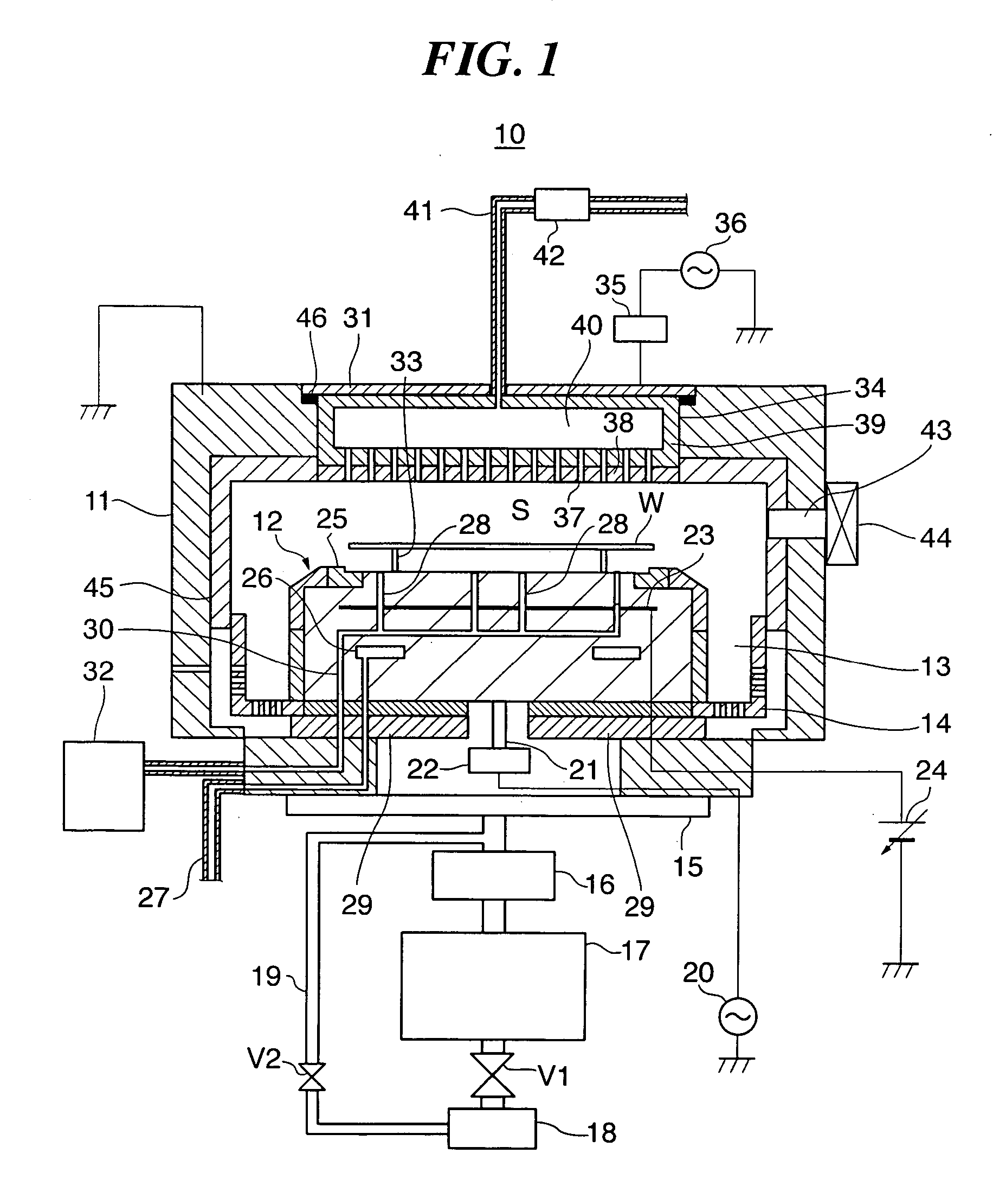
[0052] First, a sealing part and a substrate processing apparatus according to the present invention will be described. The substrate processing apparatus is constructed such as to carry out predetermined processing on substrates using a reactive active gas.

[0053]FIG. 1 is a sectional view schematically showing the construction of a plasma processing apparatus as the substrate processing apparatus according to the present embodiment. The plasma processing apparatus carries out RIE (reactive ion etching) on semiconductor wafers W as substrates, and moreover is constructed such that WLDC can also be implemented.

[0054] As shown in FIG. 1, the plasma processing apparatus 10 has a cylindrical vacuum vessel 11 (reduced pressure vessel), and the vacuum vessel 11 has a processing space S therein. A cylindrical susceptor 12 is disposed in the vacuum vessel 11 as a stage on which is mounted a semiconductor wafer W (hereinafter referred to merely as the “wafer W”) having a diameter of, for ex...

second embodiment

[0111] Next, a sealing part according to the present invention will be described.

[0112] The present embodiment is basically similar to the first embodiment described above in terms of construction and operation, differing from the first embodiment described above only in that a corrosive gas is used rather than a reactive active gas in the substrate processing apparatus. Description of features of the structure and operation that are the same as in the first embodiment will thus be omitted, with only features of the structure and operation that are different to in the first embodiment being described below.

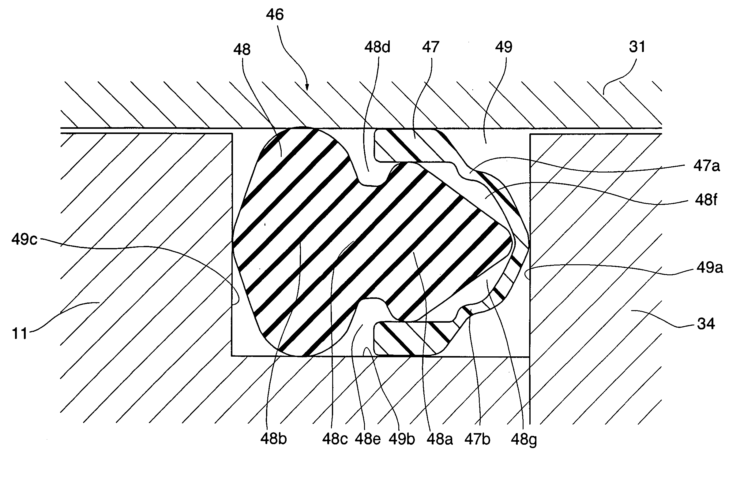
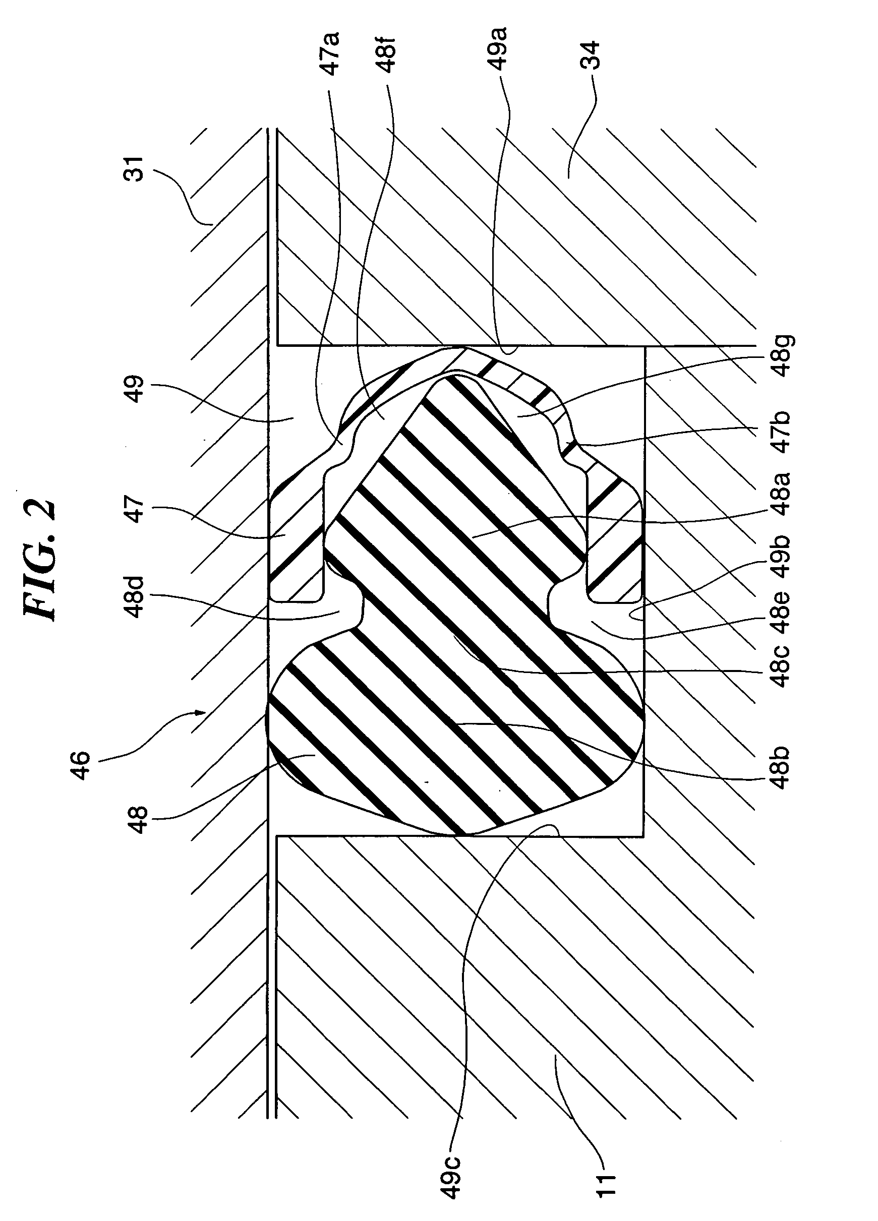
[0113]FIG. 8 is an enlarged sectional view of the sealing part according to the present embodiment. Note that a region in which the pressure is reduced substantially to a vacuum and the corrosive gas is present is located to at the top of the drawings, and a region open to the atmosphere is located at the bottom of the drawings. Hereinafter, the region to the top of the drawing w...


PUM

PropertyMeasurementUnit
diameteraaaaaaaaaa
thickness W1aaaaaaaaaa

Abstract

A sealing part that is inexpensive and enable excellent durability to be secured without the need for a predetermined sealing space as would be required for a double sealing structure. A sealing part seals an inside of a reduced pressure vessel from an outside, in which a high-elasticity polymeric material-eroding eroding substance is present and which is comprised of a substrate processing apparatus carrying out predetermined processing on a substrate housed in the reduced pressure vessel. The sealing part has a radical sealing member and a vacuum sealing member. The radical sealing member is disposed on an inside side of the reduced pressure vessel and is resistant to the eroding substance. The vacuum sealing member is made of the high-elasticity polymeric material and is disposed on an outside side of the reduced pressure vessel. At least one refuge space is formed through at least part of the radical sealing member and at least part of the vacuum sealing member being separated from one another. The radical sealing member and the vacuum sealing member are fitted together.

Description

BACKGROUND OF THE INVENTION [0001] 1. Field of the Invention [0002] The present invention relates to a sealing part and a substrate processing apparatus, and in particular relates to a sealing part used in a substrate processing apparatus that forms a plasma from a reactive active gas and processes a substrate using the plasma. [0003] 2. Description of the Related Art [0004] A plasma processing apparatus that carries out plasma processing such as etching on semiconductor wafers as substrates has a vacuum chamber the pressure inside of which can be reduced down substantially to a vacuum. The etching is carried out on a semiconductor wafer housed in the vacuum chamber using a processing gas that is turned into a plasma in the vacuum chamber. In such a plasma processing apparatus, a ring-shaped sealing part is used to seal the inside of the vacuum chamber (the vacuum) from the outside (the atmosphere) (see, for example, U.S. Pat. No. 6,689,221). In particular, for an etching apparatus ...

Claims


Application Information

Patent Timeline
Patent Type & Authority Applications(United States)
IPC IPC(8): F16J15/00
CPCF16J15/104F16J15/128H01L21/67126
Inventor HAYASHI, DAISUKEMURAMATSU, AKIRA
Owner TOKYO ELECTRON LTD
Why Eureka
Try Eureka