Arrangement with an electronically commutated external rotor motor

a technology of electronic commutation and external rotor motor, which is applied in the direction of positive displacement liquid engine, piston pump, instruments, etc., to achieve the effect of tight production tolerance, simple and economical installation, and few parts

Inactive Publication Date: 2007-04-05
EBM PAPST ST GEORGEN & -
View PDF11 Cites 16 Cited by
  • Summary
  • Abstract
  • Description
  • Claims
  • Application Information

AI Technical Summary

Benefits of technology

[0006] According to the invention, this object is achieved by providing a first external rotor separated by a first air gap from an internal stator, on one side of a liquid-tight non-ferromagnetic separating element, coupled magnetically to a second external rotor on the other side of a second air gap, in which the separating element is located. A compact design is thereby obtained: the non-ferromagnetic separating elem

Problems solved by technology

When an external-rotor motor of this kind is used for combined drive functions, the problem exists that although a compact design is desirable, on the other hand the motor must not be negatively affected by a part that is to be driven.
For examp

Method used


Image

  • Arrangement with an electronically commutated external rotor motor
  • Arrangement with an electronically commutated external rotor motor
  • Arrangement with an electronically commutated external rotor motor

Examples


Embodiment Construction

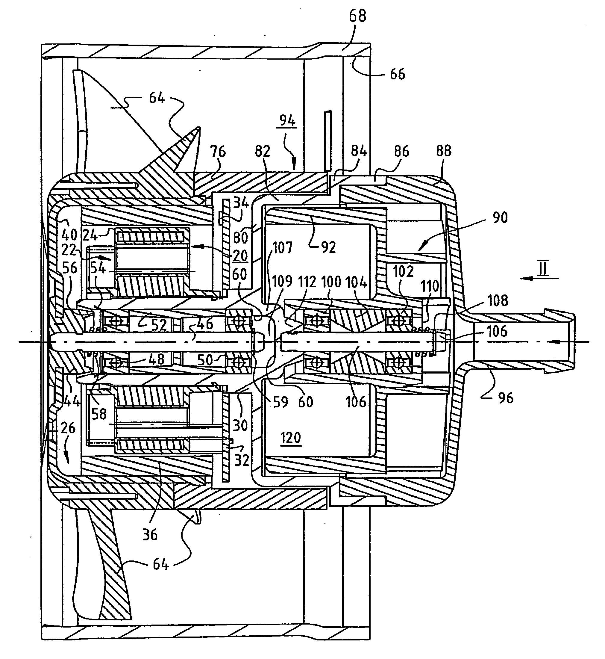
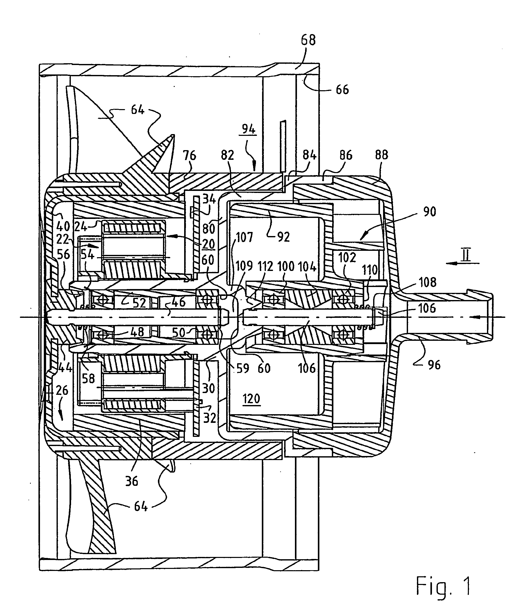
[0017]FIG. 1 shows, at approximately twice actual size, an arrangement having an electronically commutated external-rotor motor 20. The latter has an internal stator 22 of conventional design, e.g. a stator having salient poles or a claw pole stator, and the latter is separated from an external rotor 26 by a substantially cylindrical air gap 24. During operation, external rotor 26 rotates about internal stator 22, this being the reason that such motors 20 are referred to as external-rotor motors.

[0018] Internal stator 22 is mounted on a bearing tube 30, usually by being pressed on. A circuit board 32 is located to the right of internal stator 22. Located on this board are the electronic components (not shown here) that are needed for electronic commutation of motor 20, as well as a rotor position sensor 34 that is controlled by a permanent ring magnet 36 of external rotor 26. Ring magnet 36 is radially magnetized, and preferably has four rotor poles. Sensor 34 is controlled by a le...


PUM


Abstract

A motor structure resistant to liquid intrusion features two modules, the first having an electronically commutated external-rotor motor (20), which motor comprises an internal stator (22) that is arranged on a bearing tube (30) and is separated by a first air gap (24) from an external rotor (26; 92), which latter comprises a rotor cup (40) that is open at one end and is joined at its other end to a shaft (46) that is journalled in the bearing tube (30), further having a permanent-magnet arrangement (76), arranged at the open end of the rotor cup (40), for magnetic interaction with a second permanent-magnet rotor (92), forming part of the second module. The first module is separated from that second rotor (92) by a second air gap and forms therewith a magnetic coupling (94), so that a rotation of the permanent-magnet arrangement (76) brings about a rotation of that second rotor (92). A hermetic separation of the two modules is accomplished using a non-ferromagnetic separating element (82) arranged in the second air gap. The second module can safely be used to handle liquid, e.g. as a pump.

Description

FIELD OF THE INVENTION [0001] The invention relates to an arrangement having an electronically commutated external-rotor motor. BACKGROUND [0002] Thanks to their simple design, great reliability, and long service life, motors of this kind are used nowadays for a wide variety of drive functions. [0003] Typical applications are as drives for so-called equipment fans that are used to remove heat from computer housings, also as drives for small fans for direct cooling of microprocessors, drives for vacuum cleaners, etc. [0004] When an external-rotor motor of this kind is used for combined drive functions, the problem exists that although a compact design is desirable, on the other hand the motor must not be negatively affected by a part that is to be driven. For example, if this motor is driving a liquid pump or a compressor, no medium from the pump or compressor can be permitted into the motor, since that medium might otherwise damage the electronic systems of the motor or cause corros...

Claims


Application Information

Patent Timeline
IPC IPC(8): H02K7/00H02K5/10H02K5/16F04B17/00F04D13/02F04D25/06F04D29/04F04D29/60G06F1/20H01L23/473H02K7/08H02K7/14
CPCF04D13/02F04D25/06F04D29/04F04D29/60G06F1/20H01L23/473H01L2924/0002H02K5/16H02K7/08H02K7/14H01L2924/00H02K7/11H02K5/1735H02K5/128F04D13/064F04D25/064F04D19/002F04D1/00
Inventor SEIDLER, SIEGFRIEDROJO LULIC, FRANCISCOLAUFER, WOLFGANG
Owner EBM PAPST ST GEORGEN & -
Why Eureka
Try Eureka