
Linearized and balanced mixer apparatus and signal mixing method

a linearized and balanced mixer and signal mixing technology, applied in the field of communication, can solve the problems of sacrificing gain, low supply current drain, and generating intermodulation (im) distortion of the gilbert cell mixer

Active Publication Date: 2007-04-05
APPLE INC
View PDF10 Cites 51 Cited by
  • Summary
  • Abstract
  • Description
  • Claims
  • Application Information

AI Technical Summary

Benefits of technology

The present invention relates to a balanced mixer circuit and method for signal mixing in communication systems. The invention aims to improve linearization and decrease intermodulation distortion while maintaining or improving gain in low voltage, low power operating conditions. The balanced mixer circuit includes an input amplifier, a Gilbert mixer core network, a load network, and an output amplifier. The invention provides a solution for optimizing linearization under relatively low supply voltage and low supply power conditions.

Problems solved by technology

During frequency conversion, the Gilbert Cell mixer may generate intermodulation (IM) distortion when multiple signals are present at the RF port.
When the input and output circuits of the mixer are nonlinear, undesired multiplication of the RF and IF signals with each other occurs producing spurious frequencies which comprise the IM distortion component of the mixer output.
The design trade-offs for increasing mixer linearity at low voltage often sacrifices gain and low supply current drain.

Method used


Image

  • Linearized and balanced mixer apparatus and signal mixing method
  • Linearized and balanced mixer apparatus and signal mixing method
  • Linearized and balanced mixer apparatus and signal mixing method

Examples


Embodiment Construction

[0012] The following detailed description of the invention is merely exemplary in nature and is not intended to limit the invention or the application and uses of the invention. Furthermore, there is no intention to be bound by any theory presented in the preceding background of the invention or the following detailed description.

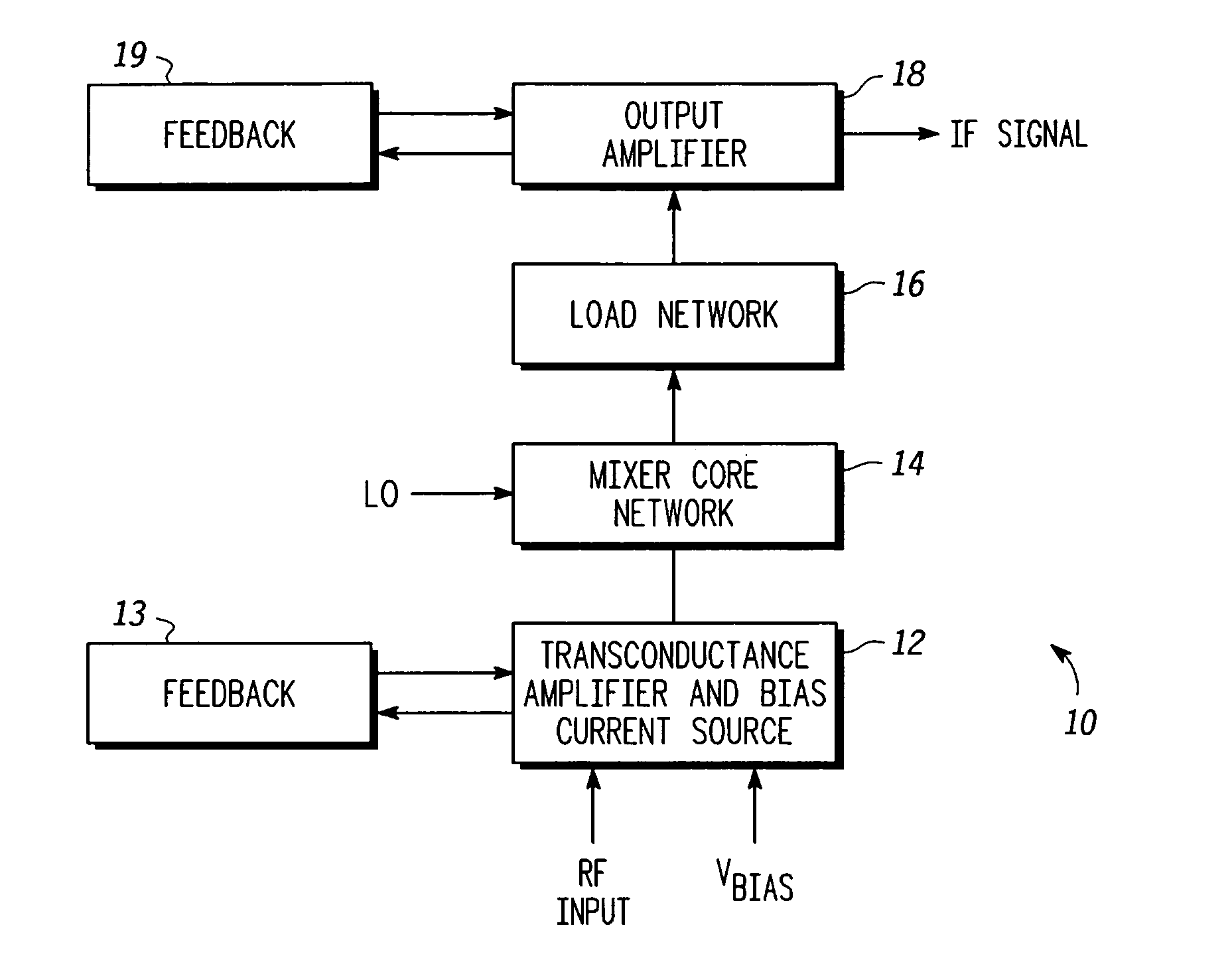
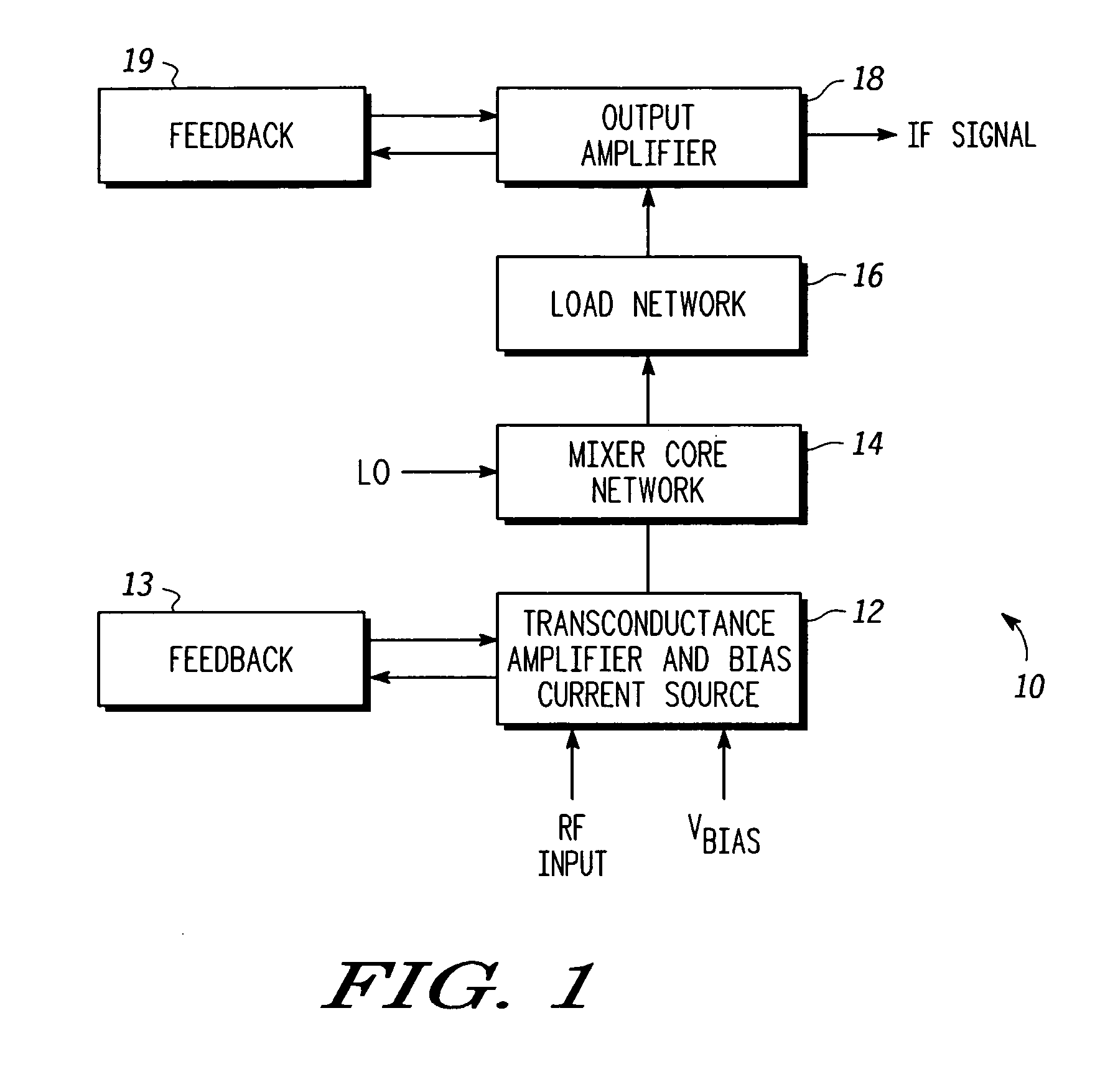
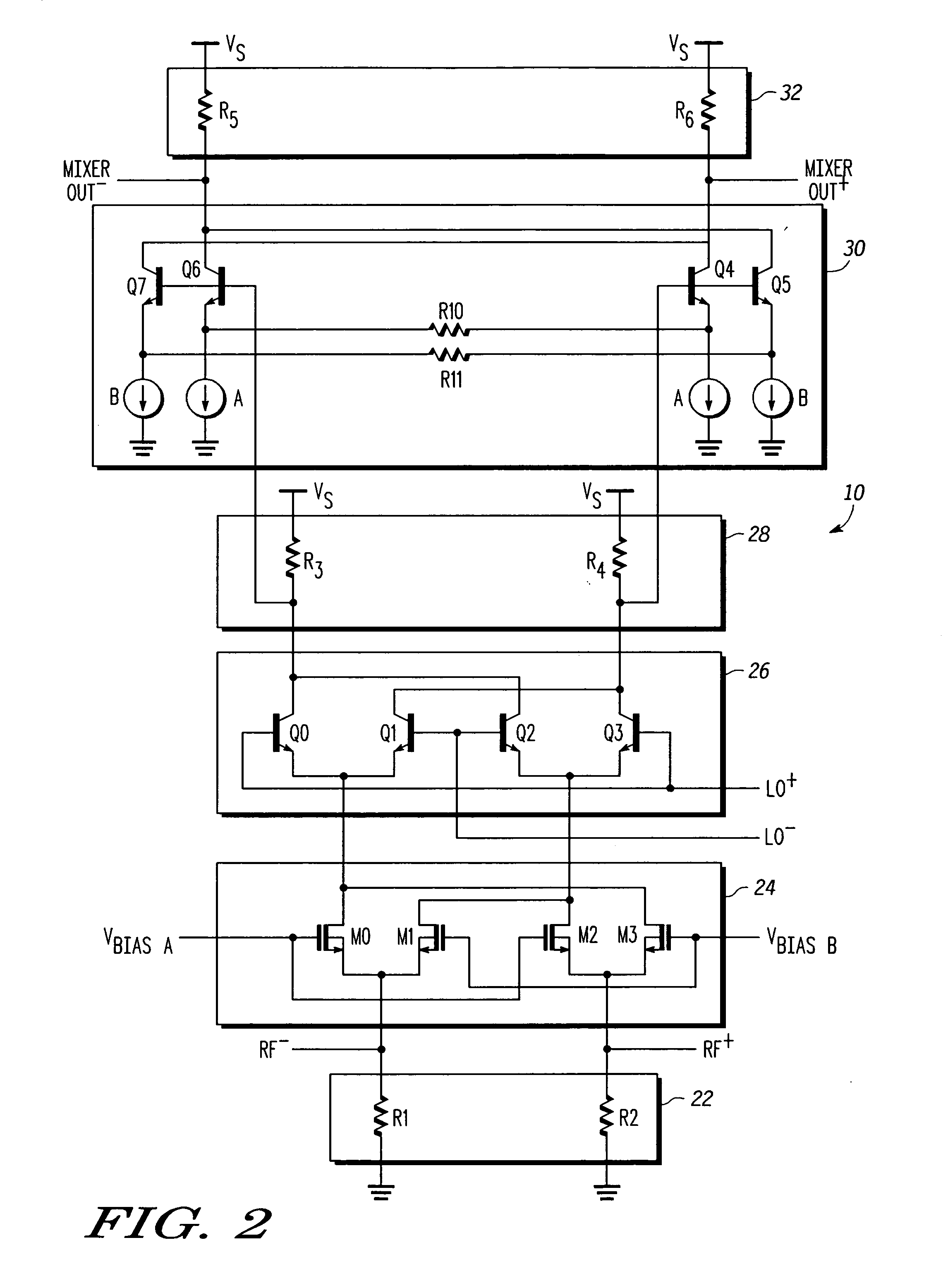
[0013] Referring to the drawings, FIG. 1 is a block diagram of an exemplary embodiment of a balanced mixer circuit 10 in accordance with the present invention. Balanced mixer circuit 10 comprises an input amplifier 12, a Gilbert mixer core network 14 coupled to the input amplifier 12, a load network 16 coupled to Gilbert mixer core network 14, and an output amplifier 18 coupled to load network 16. Input amplifier 12 is a differential transconductance amplifier and also serves as a bias current source for Gilbert mixer core network 14. Balanced mixer circuit 10 has differential inputs for receiving a Radio Frequency (RF) input signal (e.g., RFIN+ and RFIN−)...


PUM


Abstract

Method and apparatus are provided for linearized balanced signal mixing. A signal mixing circuit (10) for translating a radio frequency (RF) signal is provided comprising an input amplifier (12), a mixer network (14), and an output buffer amplifier (18). The input amplifier (12) is configured to produce an amplified RF signal and cancel an input third-order intermodulation (IM3) distortion in the amplified RF signal with a cross-coupled feedback amplifier (13). The mixer network (14) is configured to produce an intermediate frequency (IF) signal based on the amplified RF signal and a local oscillator signal. The output amplifier (18) is configured to buffer the IF signal and cancel an output IM3 distortion in the IF signal with a cross-coupled feedback amplifier (19). The input amplifier (12) and cross-coupled feedback amplifier (13) also serve as a bias current source for the mixer network (14), thus lowering the supply voltage required for the mixing circuit (10).

Description

FIELD OF THE INVENTION [0001] The present invention generally relates to communications, and more particularly relates to low power and low noise mixer circuits and related methods in communications. BACKGROUND OF THE INVENTION [0002] Mixer circuits, or mixers, are widely used in modem communication systems to translate the frequency of an input signal up or down to an Intermediate Frequency (IF) where further signal processing and demodulation can occur. This translation function is referred to herein as a frequency down-conversion or up-conversion when applied to the signal path of a receiver or transmitter. In a receiver, a front end mixer multiplies the input Radio Frequency (RF) signal with an internal Local Oscillator (LO) signal to produce sum and difference frequencies (e.g., f(mixer out)=±f(RF)±f(LO)), one of which is chosen as the desired IF. The undesired response, referred to herein as an image frequency, is typically filtered out. The IF signal is more easily amplified,...

Claims


Application Information

Patent Timeline
Patent Type & Authority Applications(United States)
IPC IPC(8): H04B1/26
CPCH03D7/145H03D7/1458H03D7/1491H03D2200/0043H03D2200/0084
Inventor RECTOR, STEPHEN
Owner APPLE INC
Learn More