Interlabial pad
a technology of interlabial pads and labiae, which is applied in the field of interlabial pads, can solve the problems of wearer inserting the interlabial pads in the wrong manner, difficulty in detecting the deviation of the interlabial pads by the finger or the labia alone when they are inserted, and difficulty in detecting the deviation of the interlabial pads when inserted, etc., to achieve the effect of suppressing the displacement of the interlabial pads
- Summary
- Abstract
- Description
- Claims
- Application Information
AI Technical Summary
Benefits of technology
Problems solved by technology
Method used
Image
Examples
first embodiment
Overall Structure of Interlabial Pad
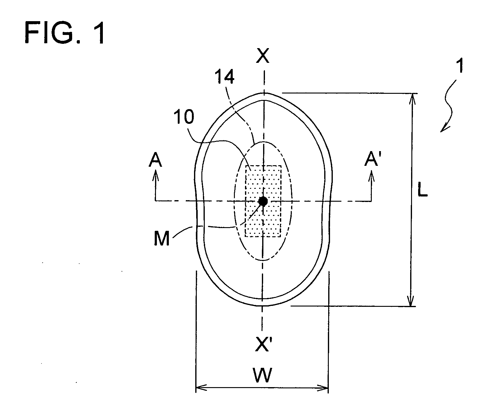
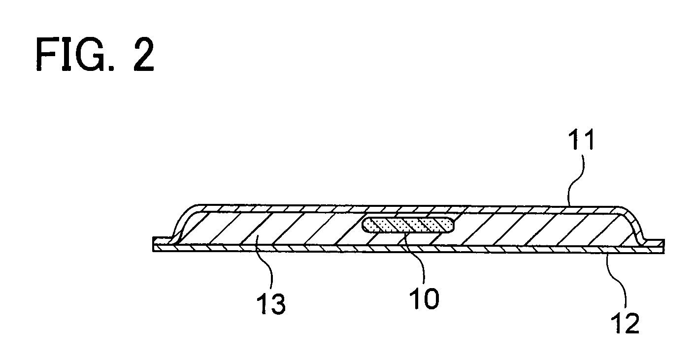
[0085]FIG. 1 is a diagram which shows an interlabial pad according to the present embodiment as viewed from the side which is to be in contact with the wearer's body. FIG. 2 is a cross-sectional view taken along line A-A′ in FIG. 1.
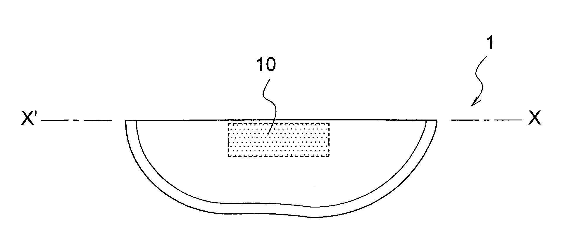
[0086] An interlabial pad 1 according to the present embodiment is formed in an oblong shape as shown in FIG. 1. As shown in FIG. 2, the interlabial pad according to the present embodiment is formed of a liquid-permeable front sheet 11, a liquid-impermeable backing sheet 12, and an absorber 13 introduced between the front sheet 11 and the backing sheet 12. The interlabial pad 1 is worn by the wearer, which is arranged at a wearer's crotch in a front to back direction of the wearer's body. The longitudinal direction of the interlabial pad is corresponding to this front to back direction. In the present specification, “front” means a front of the wearer's body, “back” means a back of the wearer's body. In the present s...
second embodiment
[0105] Next, a description will be given regarding an interlabial pad according to a second embodiment having a structure in which transition regions are provided to both ends of the highly-compressed rigid region along the longitudinal direction. FIGS. 35 through 37 are explanatory diagrams for describing the interlabial pad according the second embodiment when it is being worn.
[0106] As shown in FIG. 35, an interlabial pad 7 includes the highly-compressed rigid region 10, and transition regions 17, each of which smoothly connects the highly-compressed rigid region 10 and the other region, provided along the center line X-X′. Each of the transition regions 17 has a lower stiffness and lower resistance to being compressed than that of the highly-compressed rigid region 10. Furthermore, each of the transition regions 17 has a higher stiffness and higher resistance to being compressed than that of the peripheral region other than the highly-compressed rigid region 10. With such an ar...
third embodiment
[0107] Next, a description will be given regarding an interlabial pad the back face of which includes a pocket for allowing the insertion of the wearer's finger. FIG. 38 is a diagram which shows an interlabial pad including a finger insertion pocket having a finger insertion opening formed on the backing sheet. FIGS. 39 and 40 are diagrams which show the interlabial pad when it is being worn.
[0108] As shown in FIG. 38, an interlabial pad 8 according to the present embodiment includes a finger insertion pocket 18. Such an arrangement allows the wearer to position the wearer's sensitive finger cushion on the high-compression stiff portion 10 as shown in FIGS. 39 and 40. This allows the wearer to form a protrusion while guiding the highly-compressed rigid region 10 to a proper position between the labia minora. This allows the wearer to wear the interlabial pad 8 at a proper position in a more assured manner.
PUM
 Abstract
Description
Claims
Application Information
 - R&D
- Intellectual Property
- Life Sciences
- Materials
- Tech Scout
- Unparalleled Data Quality
- Higher Quality Content
- 60% Fewer Hallucinations
Browse by: Latest US Patents, China's latest patents, Technical Efficacy Thesaurus, Application Domain, Technology Topic, Popular Technical Reports.
© 2025 PatSnap. All rights reserved.Legal|Privacy policy|Modern Slavery Act Transparency Statement|Sitemap|About US| Contact US: help@patsnap.com


