Method and system for controlling a batch process

a batch process and control system technology, applied in automatic control, electric controllers, instruments, etc., can solve the problems of increasing the pressure within the tank, reducing the pressure, and using a number of independently operating loops. to achieve the effect of facilitating the control of the batch process

Active Publication Date: 2007-04-05
FISHER-ROSEMOUNT SYST INC
View PDF9 Cites 60 Cited by
  • Summary
  • Abstract
  • Description
  • Claims
  • Application Information

AI Technical Summary

Benefits of technology

[0012] A first principles model may be used to simulate a batch process, and the first principles model may be used to configure a multiple-input/multiple-output control routine for controlling the batch process. The first principles model may generate estimates of batch parameters that cannot, or are not, measured during operation of the actual batch process. An example of such a parameter may be a rate of change of a component (e.g., a production rate, a cell growth rate, etc.) of the batch process. The first principles model and the configured multiple-input/multiple-output control routine may be used to facilitate control of the batch process.
[0013] For exa

Problems solved by technology

However, in certain cases, the use of a number of independently operating, single input/single output control loops is not very effective because the process variables or process outputs being controlled are effected by more than a single process input and, in fact, each process input may effect the state of many process outputs.
However, in this situation, the operation of the temperature control loop in changing the setting of one of the input valves to control the temperature within the tank may cause the pressure within the tank to increase, which, for example, causes the pressure loop to open the outlet valve to decrease the pressure.
As will be understood in this example, the single input/single output control loops may cause the process outputs (in this case, throughput, temperature and pressure) to oscillate without ever reaching a steady state condition, which is undesirable.
With regard to batch processes (and batch process components of semi-continuous processes), pertinent process variables often cannot be measured during operation

Method used


Image

  • Method and system for controlling a batch process
  • Method and system for controlling a batch process
  • Method and system for controlling a batch process

Examples


Embodiment Construction

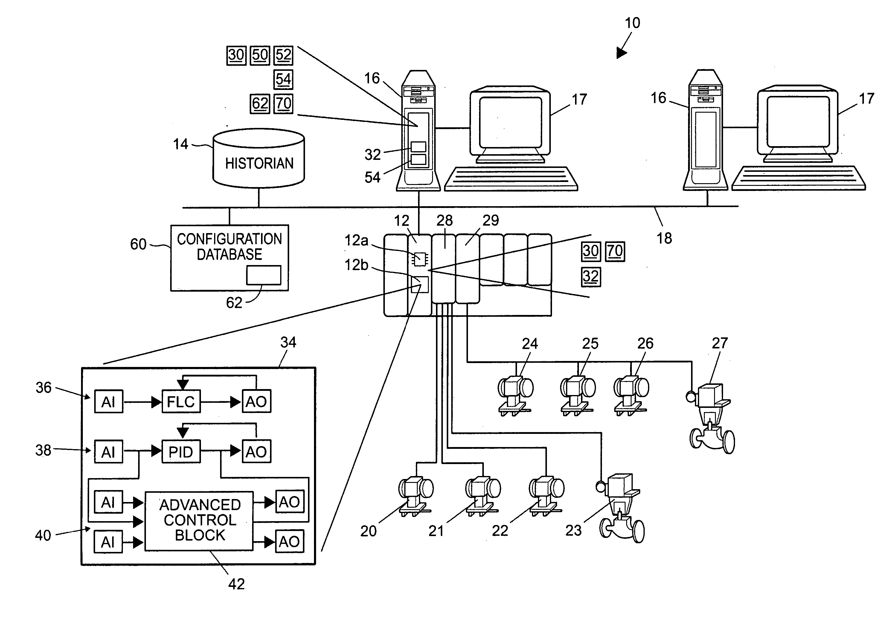
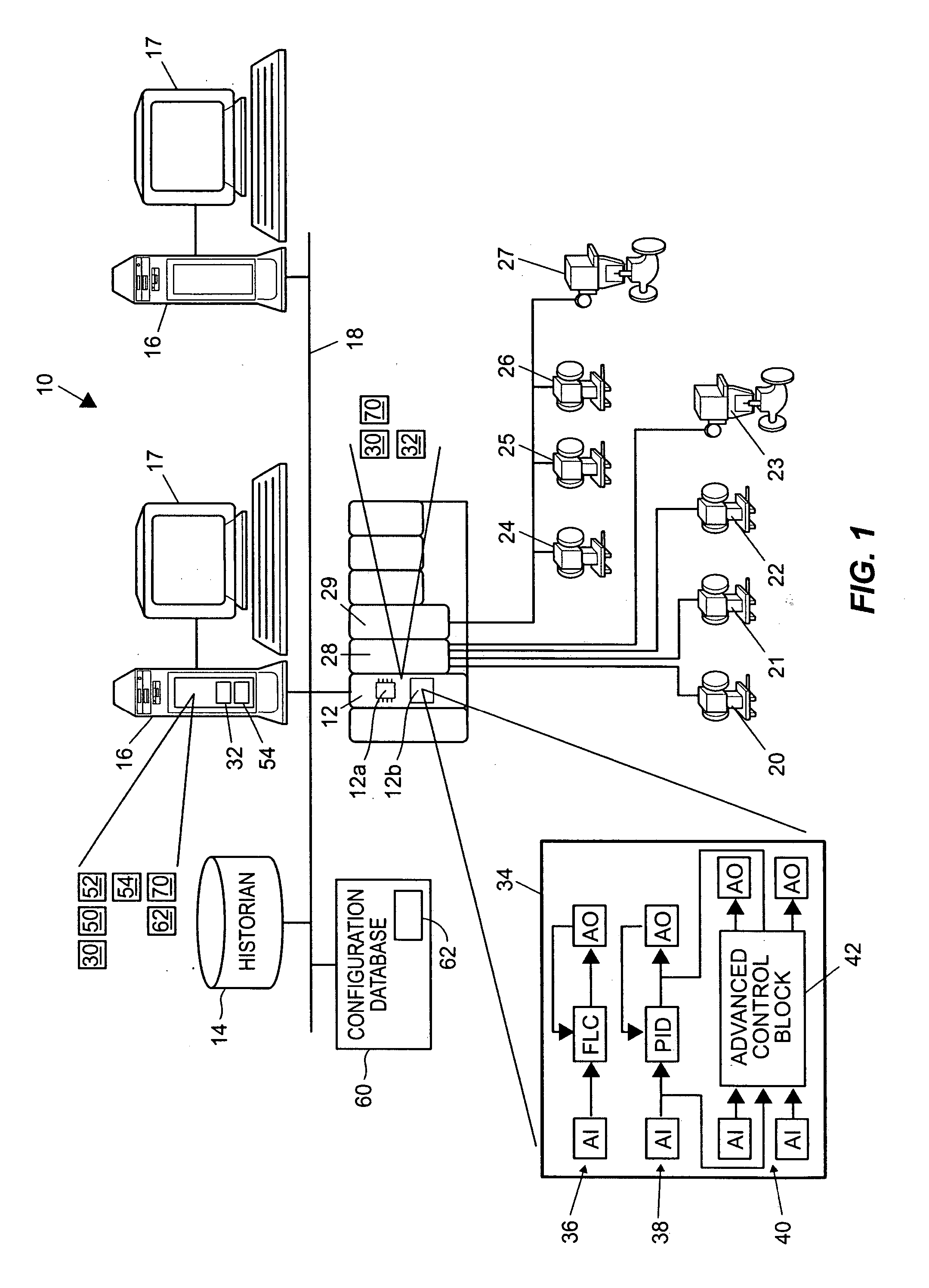
[0024] Referring now to FIG. 1, a process control system 10 includes a process controller 12 connected to a data historian 14 and to one or more host workstations or computers 16 (which may be any type of personal computers, workstations, etc. each having a display screen 17), via a communications network 18. The controller 12 is also connected to field devices 20-27 via input / output (I / O) cards 28 and 29. The communications network 18 may be, for example, an Ethernet communications network or any other suitable or desirable communications network while the data historian 14 may be any desired type of data collection unit having any desired type of memory and any desired or known software, hardware or firmware for storing data. The controller 12, which may be, by way of example, the DeltaV™ controller sold by Fisher-Rosemount Systems, Inc., is communicatively connected to the field devices 20-27 using any desired hardware and software associated with, for example, standard 4-20 ma d...


PUM


Abstract

A first principles model may be used to simulate a batch process, and the first principles model may be used to configure a multiple-input/multiple-output control routine for controlling the batch process. The first principles model may generate estimates of batch parameters that cannot, or are not, measured during operation of the actual batch process. An example of such a parameter may be a rate of change of a component (e.g., a production rate, a cell growth rate, etc.) of the batch process. The first principles model and the configured multiple-input/multiple-output control routine may be used to facilitate control of the batch process.

Description

TECHNICAL FIELD [0001] This invention relates generally to process control systems and, more particularly, to systems for controlling and / or modeling batch processes. DESCRIPTION OF THE RELATED ART [0002] Process control systems, such as distributed or scalable process control systems like those used in chemical, petroleum or other processes, typically include one or more process controllers communicatively coupled to each other, to at least one host or operator workstation and to one or more field devices via analog, digital or combined analog / digital buses. The field devices, which may be, for example valves, valve positioners, switches and transmitters (e.g., temperature, pressure and flow rate sensors), perform functions within the process such as opening or closing valves and measuring process parameters. The process controller receives signals indicative of process measurements made by the field devices and / or other of information pertaining to the field devices, uses this inf...

Claims


Application Information

Patent Timeline
IPC IPC(8): G05B11/01G05B13/02
CPCG05B13/041G05B17/02G05B13/048G05B13/04
Inventor BLEVINS, TERRENCE L.MCMILLAN, GREGORY K.BOUDREAU, MICHAEL A.
Owner FISHER-ROSEMOUNT SYST INC
Why Eureka
Try Eureka