Control system

a control system and control system technology, applied in the field of control systems, can solve the problems of requiring a large number of steps, and achieve the effects of preventing installation errors, reducing the number of steps taken after the system configuration change, and reducing the number of steps

Inactive Publication Date: 2007-04-05
YOKOGAWA ELECTRIC CORP
View PDF6 Cites 49 Cited by
  • Summary
  • Abstract
  • Description
  • Claims
  • Application Information

AI Technical Summary

Benefits of technology

[0061] Since the position detection section detects the position where the home node is installed, if the operator misunderstands the installation position, the correct installation position is displayed on the display screen of the display section and thus an installation mistake can be prevented.
[0062] Since the switching hubs are provided between the network and the system component nodes, only the packets other than those transmitted to the system component nodes in the same switching hub are transmitted to the network. Accordingly, the traffic of the network can be lessened.
[0063] The self-learning section of the controller learns more appropriate control functions by transmitting and receiving the input / output signals to / from the sensor and the actuator and reflects the control functions on the storage section of the management node, so that the need for the operator to find the optimum control function from the operation and monitor screen of the display section and store the optimum control function in the storage section is eliminated. Accordingly, the number of steps taken after the system configuration is changed can be reduced.

Problems solved by technology

However, if one system component node is changed, for example, at a job site in the plant, it is necessary each time to correct the relevant DBs 11 to 15 of the system definition information group and generate screens of the display section, set the addresses of the system component nodes, and download the control functions in accordance with the corrected definition information, and thus an enormous number of steps are required; this is a problem.

Method used


Image

  • Control system
  • Control system
  • Control system

Examples


first embodiment

[0073] [First Embodiment]

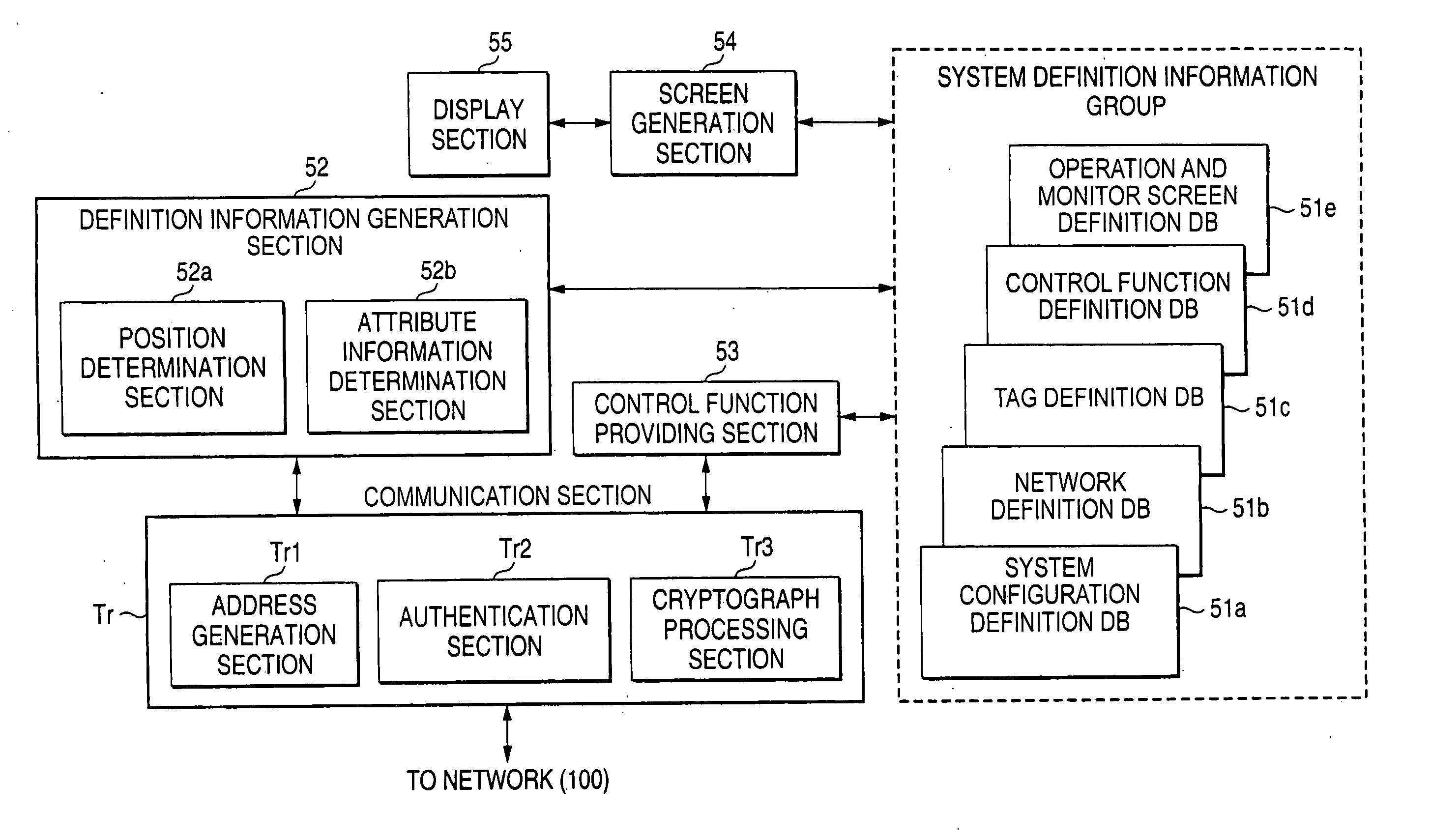
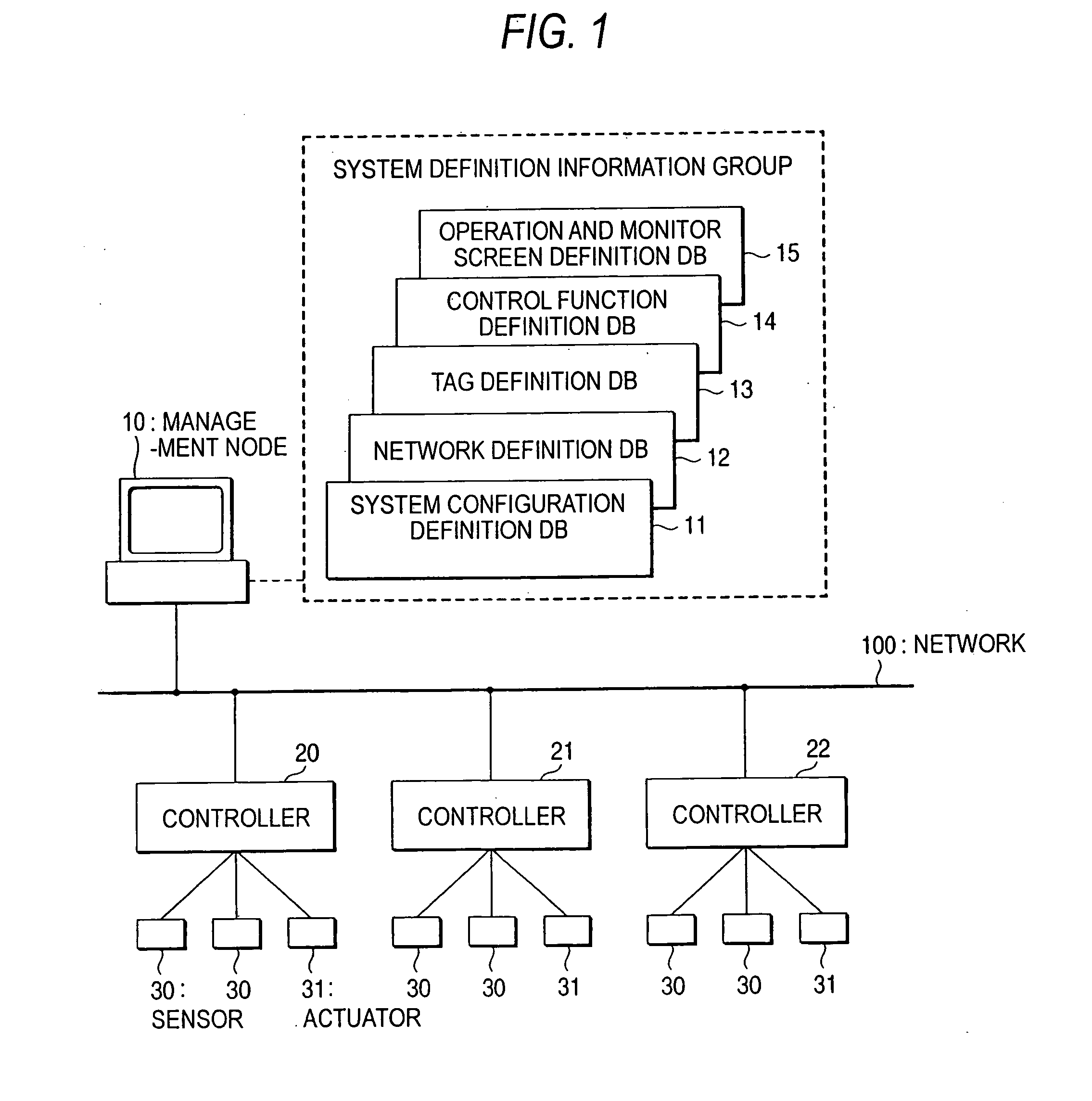
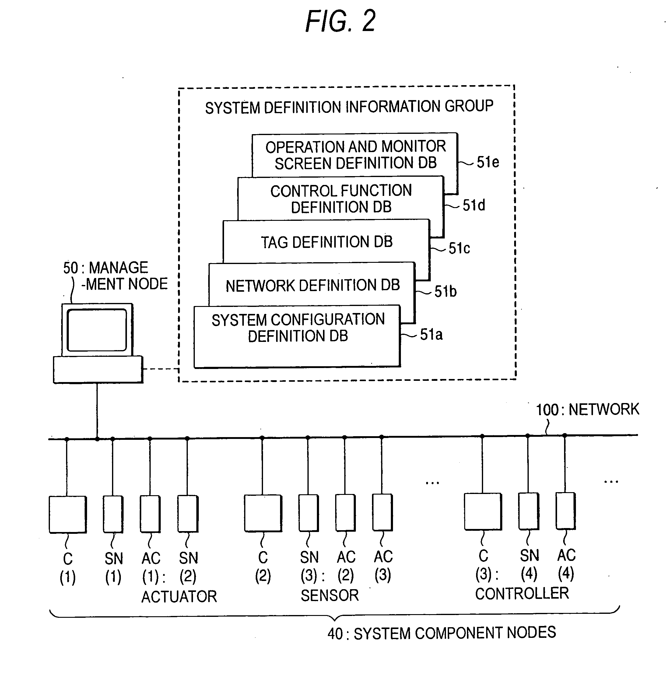
[0074]FIG. 2 is a diagram of a configuration to show a first embodiment of the invention. FIG. 3 is a block diagram to show a configuration of a system component node 40. FIG. 4 is a diagram to show a configuration of a management node 50. Parts identical with those in FIG. 1 are denoted by the same reference numerals in FIGS. 2 to 4 and will not be discussed again. In FIGS. 2 to 4, controllers C(1) to C(3), sensors SN(1) to SN(4), and actuators AC(l) to AC(4) are connected to a network 100 in stead of the controllers 20 to 22, the sensors 30, and the actuators 31 (in FIG. 2, three controllers, four sensors, and four actuators are connected by way of example, but any numbers of controllers, sensors, and actuators may be connected) Here, the controllers C(1) to C(3), the sensors SN(1) to SN(4), and the actuators AC(1) to AC(4) are called system component nodes 40. Unlike the apparatus shown in FIG. 1, the system component nodes 40 are not connected in a plura...

second embodiment

[0128] [Second Embodiment]

[0129]FIG. 6 is a diagram of a configuration to show a second embodiment of the invention. Parts identical with those in FIGS. 2 to 4 are denoted by the same reference numerals in FIG. 6 and will not be discussed again and are not shown either in the figure. A network 100 is provided with switching hubs SH1 to SH3 each having a plurality of ports. The switching hubs SH1 to SH3 are provided between the network 100 and system component nodes 40. Sensors SN(1) to SN(4) and actuators AC(1) to AC(4) for transmitting and receiving a packet to and from controllers C(1) to C(3) are connected to ports of the same switching hubs SH1 to SH3. Each of the switching hubs SH1 to SH3 has an address table for retaining the addresses of the system component nodes 40 connected to the ports. Further, each port of the switching hubs SH1 to SH3 has bridge means of a bridge function.

[0130] The operation of such an apparatus is as follows:

[0131] The operation of the apparatus sh...

third embodiment

[0134] [Third Embodiment]

[0135]FIG. 7 is a diagram of a configuration to show a third embodiment of the invention and shows an example of applying the invention to BA. Parts identical with those in FIGS. 2 to 4 are denoted by the same reference numerals in FIG. 7 and will not be discussed again. In FIG. 7, controllers C(4) to C(6), sensors SN(5) to SN(7), and actuators AC (5) to AC (8) are provided in place of the controllers C(1) to C(3), the sensors SN(1) to SN(4), and the actuators AC(1) to AC (4), and are connected to a network. The sensors SN(5) to SN(7), the controllers C4 to C6, and the actuators AC(5) to AC(8) are system component nodes 40. For example, the sensors SN(5) to SN(7) are an authentication sensor, a human body sensor, and a temperature sensor respectively, and the actuators AC(5) and AC (8) are an electric lock of a door not shown and an air conditioner respectively and the actuators AC (6) and AC(7) are lighting.

[0136] The management node 50 is newly provided w...


PUM


Abstract

It is an object to provide a control system wherein a system configuration can be changed in a short time. To do this, the invention adds improvement to a control system established through a network. The control system includes: a plurality of system component nodes each having a communication section for generating a unique global address by the system component node itself upon connection to the network, and for transmitting the generated global address, attribute information of the system component node and installation position information of the system component node, to the network; and a management node for monitoring and operating the system component nodes through the network and managing control of the whole control system, wherein the management node includes: a communication section for performing communication through the network; a storage section for storing definition information of the system component nodes; a display section for displaying an operation and monitor screen; a definition information generation section for generating definition information based on the global address, the attribute information and the position information which are acquired through the network, and for storing the definition information in the storage section; a screen generation section for making the display section display the operation and monitor screen of the system component nodes from the definition information in the storage section; and a control function providing section for reading information defining an operation of the system component node from the storage section, and for outputting the read information to the communication section.

Description

TECHNICAL FIELD [0001] This invention relates to a control system established through a network, and more particularly, to a control system wherein a system configuration can be changed in a short time. BACKGROUND ART [0002] Control systems are available on various scales from a large-scale control system as called IA (Industrial Automation) (for example, control and monitor of a plant), to a medium-scale control system as called BA (Building Automation) (for example, control and monitor of air conditioning, lighting, etc., of a building), to a small-scale control system as called LA (Laboratory Automation) (for example, control and monitor of a small number of (several to several ten) machines installed in a laboratory). [0003] Such a control system displays various pieces of information required for controlling and running the system on a display screen of a display section of a management node for managing control of the whole control system and if an abnormality occurs in the sy...

Claims


Application Information

Patent Timeline
Patent Type & Authority Applications(United States)
IPC IPC(8): G06F15/173G06F13/00G05B19/042G05B23/02
CPCG05B19/042G05B2219/21028
Inventor TOMITA, TOSHIHIROHOSHI, TETSUO
Owner YOKOGAWA ELECTRIC CORP
Why Eureka
Try Eureka