Multi-cyclone dust collector for vacuum cleaner and vacuum cleaner employing the same

Inactive Publication Date: 2007-04-12
SAMSUNG ELECTRONICS CO LTD
View PDF23 Cites 130 Cited by
  • Summary
  • Abstract
  • Description
  • Claims
  • Application Information

AI Technical Summary

Benefits of technology

[0029] According to the multi-cyclone dust collector for vacuum cleaner and the vacuum cleaner as described above, dust collecting efficiency for separating and collecting contaminants is substantially higher than conventional cyclone units because a space forming an upwardly whirling air current is separated from a contaminants collecting space in each of the first and second cyclone units.
[0030] According to the multi-cyclone dust collector for a vacuum cleaner and the vacuum cleaner as described above, the arrangement where the second cyclone unit is disposed under the firs

Problems solved by technology

Furthermore, the conventional cyclone dust collectors cannot separate fine contaminants.
However, the multi-cyclone dust collector still has a problem: the rising

Method used


Image

  • Multi-cyclone dust collector for vacuum cleaner and vacuum cleaner employing the same
  • Multi-cyclone dust collector for vacuum cleaner and vacuum cleaner employing the same
  • Multi-cyclone dust collector for vacuum cleaner and vacuum cleaner employing the same

Examples


Embodiment Construction

[0041] Hereinafter, certain exemplary embodiments of the present invention will be described in detail with reference to the accompanying drawings.

[0042] The matters defined in the description, such as a detailed construction and elements thereof, are provided to assist in a comprehensive understanding of the invention. Thus, it is apparent that the present invention may be carried out without those defined matters. Also, well-known functions or constructions are omitted to provide a clear and concise description of exemplary embodiments of the present invention.

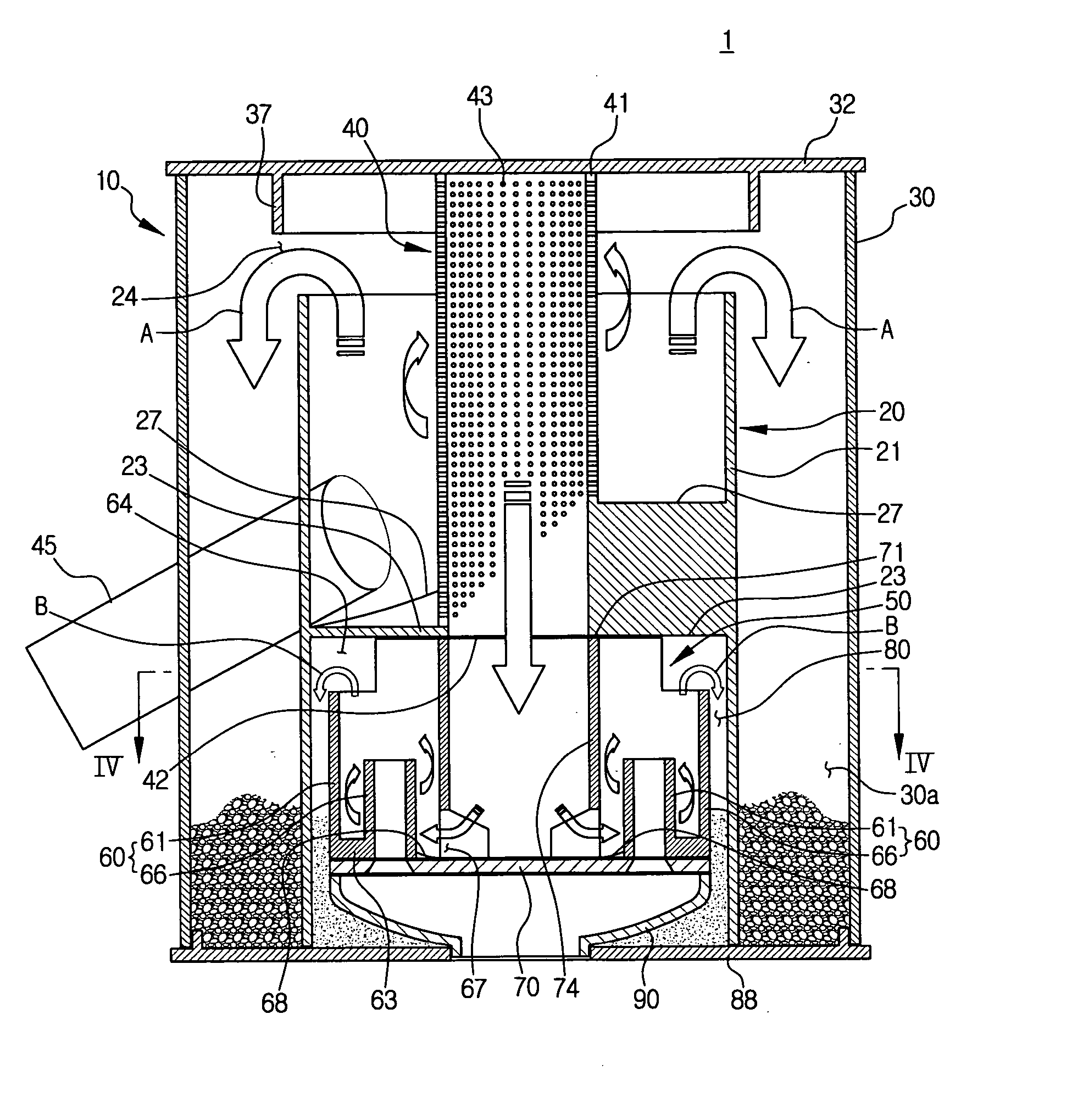
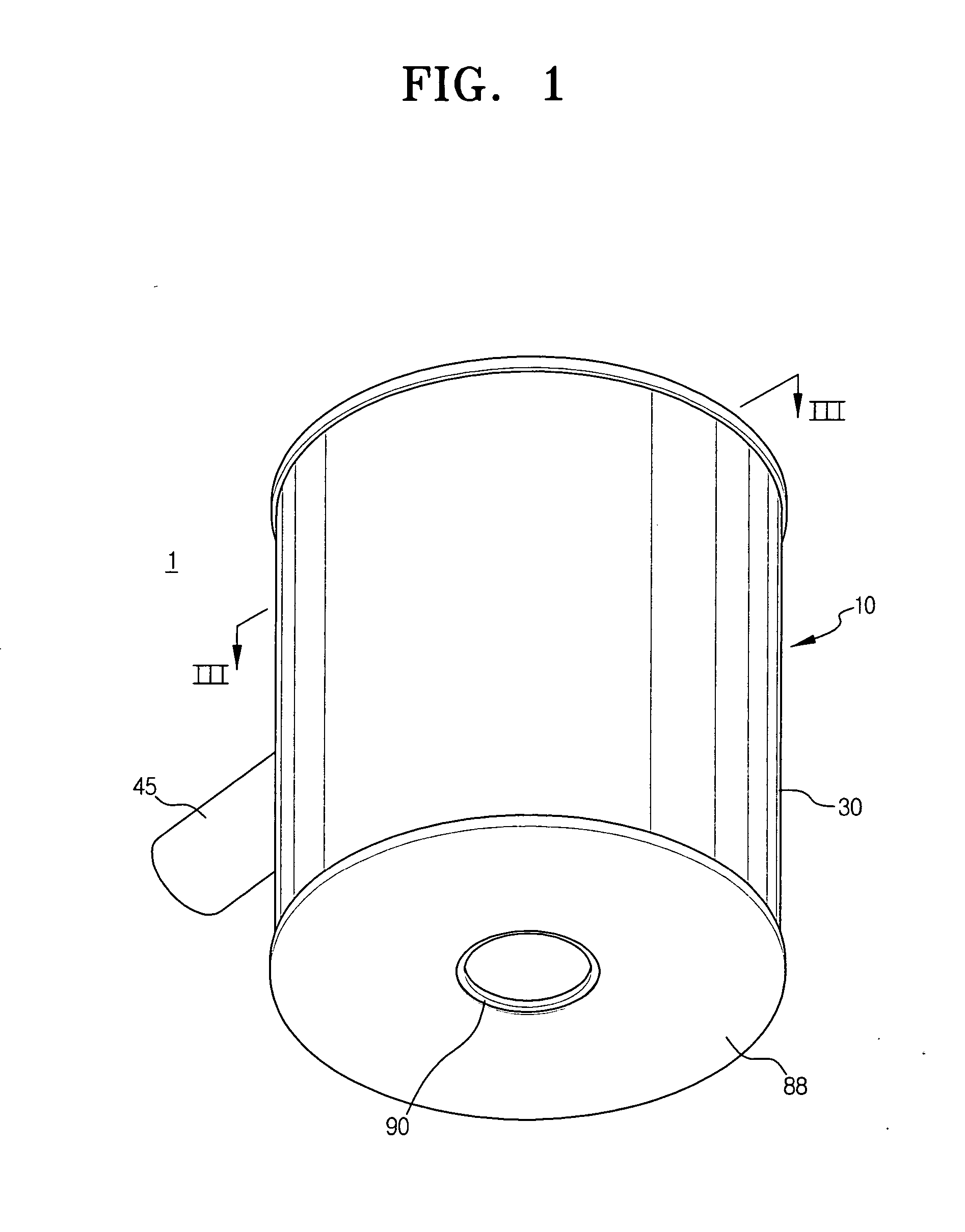
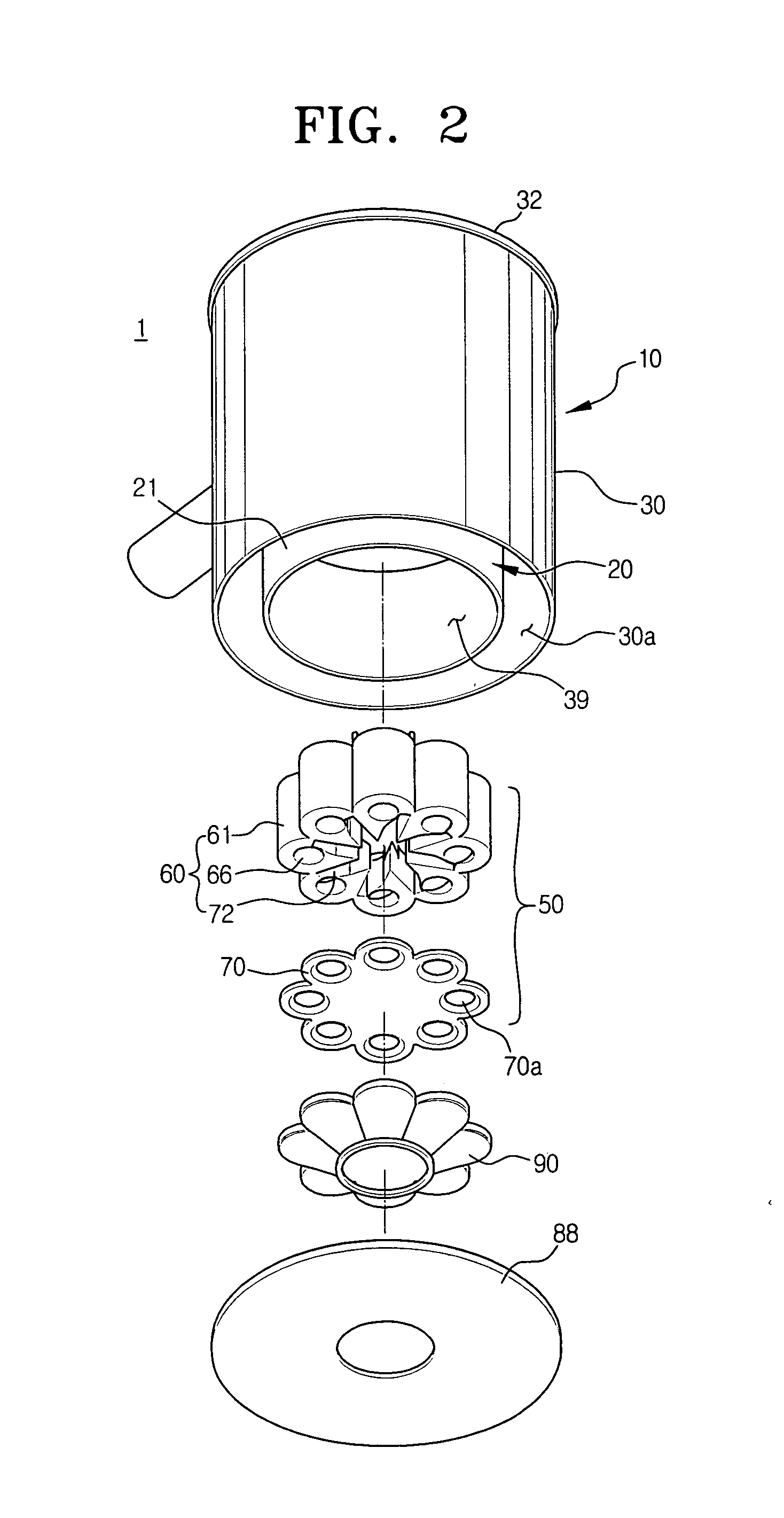
[0043] Referring to FIGS. 1 to 3, a multi-cyclone dust collector 1 according to an embodiment of the present invention includes a first cyclone unit 10 and a second cyclone unit 50.

[0044] The first cyclone unit 10 takes air, which is sucked through a suction brush 110 (see FIG. 6) and contains contaminants (hereinafter, referred to as a dust-laden air), and forces the air to enter into a lower portion of the first cyclone...


PUM

PropertyMeasurementUnit
Centrifugal forceaaaaaaaaaa
Shapeaaaaaaaaaa

Abstract

The present invention relates to a multi-cyclone dust collector and a vacuum cleaner employing the same that forms an upwardly whirling air current so as to separate contaminants. The multi-cyclone dust collector for the vacuum cleaner includes a first cyclone unit causing dust-laden air sucked through a lower portion of the first cyclone unit to form a first upwardly whirling air current so as to separate contaminants from the dust-laden air by centrifugal force, and a second cyclone unit disposed under the first cyclone unit and making partially clean air, which is discharged from the first cyclone unit and then sucked in a lower portion of the second cyclone unit, to form a second upwardly whirling air current so as to separate dust from the partially clean air by centrifugal force.

Description

CROSS-REFERENCE TO RELATED APPLICATIONS [0001] This application claims the benefit under 35 U.S.C. § 119(a) of Korean Patent Application No. 2005-95417 filed on Oct. 11, 2005 in the Korean Intellectual Property Office, the contents of which is incorporated herein by reference in its entirety. BACKGROUND OF THE INVENTION [0002] 1. Field of the Invention [0003] The present invention relates to a vacuum cleaner. More particularly, the present invention relates to a multi-cyclone dust collector for a vacuum cleaner. [0004] 2. Description of the Related Art [0005] Generally, a vacuum cleaner sucks dust-laden air that contains contaminants such as dust or dirt by suction force generated by a vacuum generator. When the dust-laden air passes through a dust collecting apparatus disposed in a main body of the vacuum cleaner, contaminants are separated from the dust-laden air and collected in the dust collecting apparatus. Then, clean air is discharged out of the vacuum cleaner. [0006] The dus...

Claims


Application Information

Patent Timeline
IPC IPC(8): B01D45/12A47L9/16
CPCA47L9/1608A47L9/1625A47L9/1641A47L9/1683B04C5/13B04C5/185B04C5/26A47L9/10A47L9/16
Inventor KIM, TAK-SOO
Owner SAMSUNG ELECTRONICS CO LTD
Why Eureka
Try Eureka