Removal of Residual Concrete from Ready Mixed Concrete Drums

a technology of ready mixed concrete and residual concrete, which is applied in the directions of water supply installation, cleaning using liquids, transportation and packaging, etc., can solve the problems of reducing the volume of concrete that the truck can legally haul, adversely affecting the quality of ready mixed concrete, and increasing the weight of the truck when empty, so as to reduce the energy required to accomplish the cleaning

Active Publication Date: 2007-04-12
BLASTERS
View PDF13 Cites 18 Cited by
  • Summary
  • Abstract
  • Description
  • Claims
  • Application Information

AI Technical Summary

Benefits of technology

[0041] Still another advantage is that the pressure and flow forces generated by the novel apparatus hydraulically lifts concrete from the drum with its impingement forces, i.e., the residual co

Problems solved by technology

Over time, the drum is laden with residual concrete that gradually builds up, substantially increasing the weight of the truck when empty and substantially reducing the volume of concrete that the truck can legally haul.
The residual concrete also adversely affects the quality of the ready mixed concrete carried by the truck.
The shortcomings of this well-known procedure are many—the entry into the work space is confined and therefore requires confined space entry permitting, the worker may experience eye injuries, tripping or slipping and falling, and exposure to silica and other harmful particles as the concrete is chipped.
Moreover, the worker's hearing is adversely affected in view of the small size of the confined space where the pneumatic chipping hammer is operated, the worker may damage the truck drum and the helical fins or blades when breaking through a chunk of concrete, an

Method used


Image

  • Removal of Residual Concrete from Ready Mixed Concrete Drums
  • Removal of Residual Concrete from Ready Mixed Concrete Drums
  • Removal of Residual Concrete from Ready Mixed Concrete Drums

Examples


Embodiment Construction

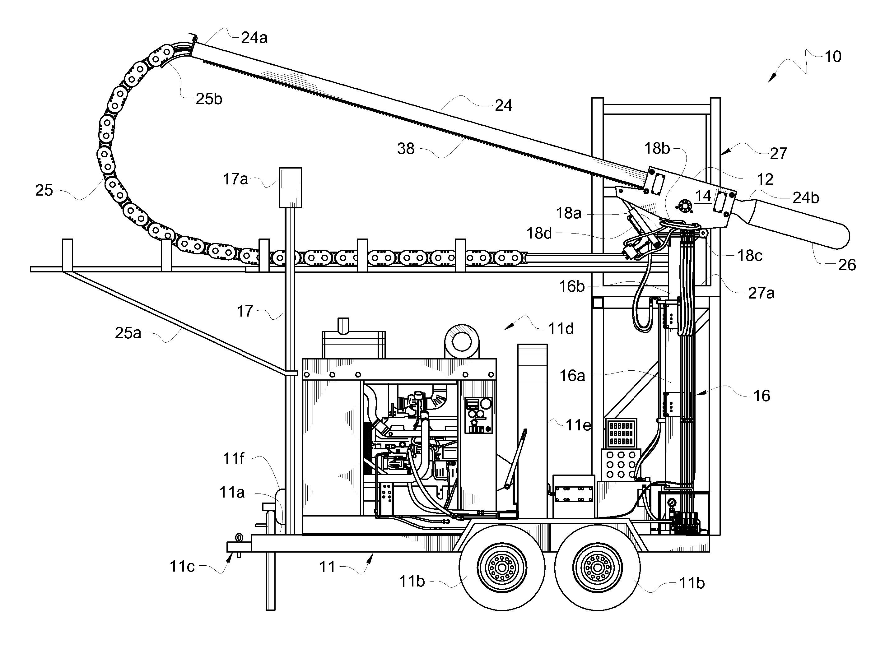
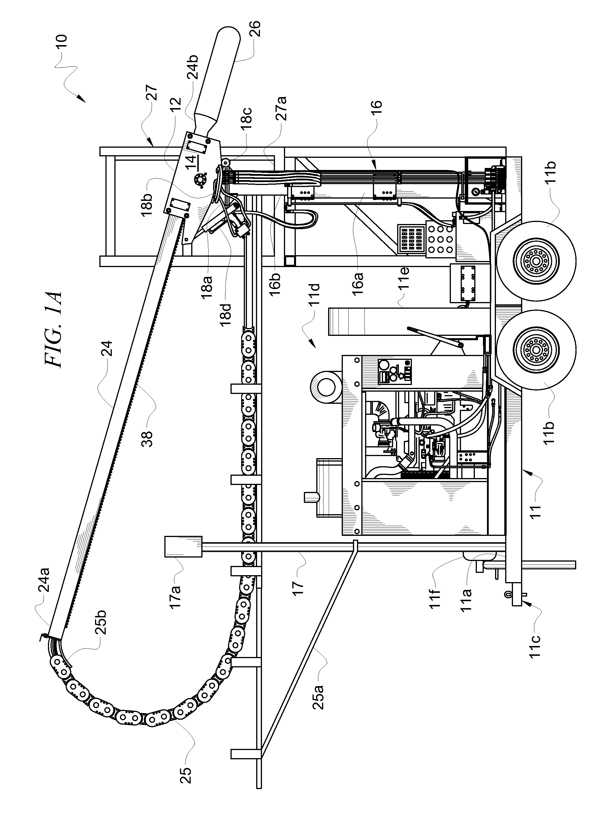
[0060] Referring now to FIG. 1A, it will there be seen that an illustrative embodiment of the invention is denoted as a whole by the reference numeral 10. FIG. 1A depicts trailer 11 having trailer bed 11a, wheels 11b, hitch assembly 11c, diesel engine 11d, pump belt guard 11e, and diesel-powered water booster pump 11f.

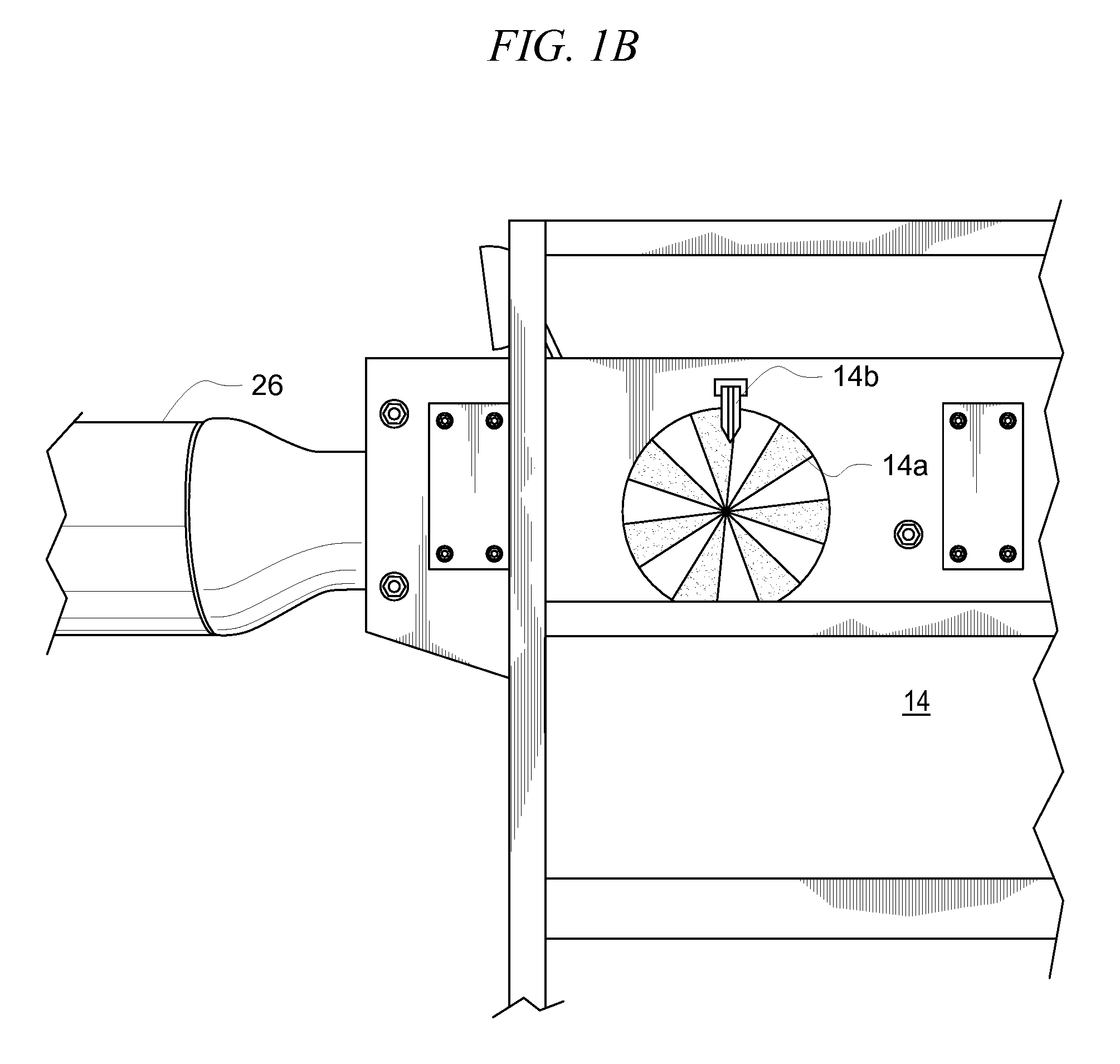
[0061] Hollow housing 12 is mounted atop hydraulic motor mount assembly 14 and said hydraulic motor mount assembly 14 is disposed in surmounting relation to tower 16. Tower 16 includes lower tube 16a that telescopically receives movable upper tube 16b therewithin so that the height of tower 16 is adjustable. The telescopic movement is preferably controlled by an internal hydraulic cylinder, not depicted.

[0062] A hinge assembly surmounts upper tower 16b. Top plate 18a surmounts upper tower 16b, and support plate 18b is hingedly secured to top plate 18a by hinge 18c. Hydraulic motor mount assembly 14 is mounted atop said support plate 18b. Hinge assembly is depicted in...


PUM

PropertyMeasurementUnit
Angleaaaaaaaaaa
Angleaaaaaaaaaa
Angleaaaaaaaaaa

Abstract

Residual concrete in the drum of a ready mixed concrete truck is removed by high-pressure water. A nozzle is mounted on the leading end of a torpedo-shaped nozzle housing that is hingedly mounted to an elongate boom. The boom enters the mouth of the drum at an angle that matches the angle of the drum. The hinge allows the nozzle housing to pivot with respect to the elongate boom so that the nozzle is close to the residual concrete. The boom is retracted toward the mouth with the drum rotating in the mix direction and the nozzle oscillating so that it cuts through a swath of concrete. As the boom retracts, the torpedo-shaped nozzle housing maintains the nozzle close to the residual concrete on the drum and both sides of the helical fins. The nozzle sweeps an arc from about eighty to one hundred twenty degrees as it oscillates.

Description

CROSS-REFERENCE TO RELATED DISCLOSURES [0001] This disclosure is a continuation-in-part of U.S. patent application Ser. No. 11 / 240,117, filed by the same inventors on Sep. 30, 2005, having the same title as this disclosure.BACKGROUND OF THE INVENTION [0002] 1. Field of the Invention [0003] This invention relates, generally, to methods for removing concrete from the inside of ready mixed concrete truck drums. More particularly, it relates to methods that do not require a worker to enter into the drum, thereby protecting the worker from various occupational hazards. [0004] 2. Description of the Prior Art [0005] Ready mixed concrete drums are rotatably mounted on concrete trucks so that the concrete in the drum can be continuously mixed, typically with the drum rotating in a clockwise direction, as it is transported from a concrete batching facility to a job site. Upstanding helical fins or blades are mounted on the interior walls of the rotating drum so that concrete at the closed end...

Claims


Application Information

Patent Timeline
IPC IPC(8): B08B9/00B08B3/12
CPCB08B9/093B28C5/4203Y10T137/8807
Inventor BOOS, FREDERICK A.BOOS, SCOTT F.CHARO, MICHAEL W.
Owner BLASTERS
Why Eureka
Try Eureka