Low loss ultrasound transducers

a low-loss, ultrasound-based technology, applied in the field of ultrasound systems, can solve the problems of reducing the reliability, capability, and life span of the transducer, and loss in the transducer, and loss is particularly significan

Inactive Publication Date: 2007-04-12
CLEANING TECH GROUP
View PDF0 Cites 38 Cited by
  • Summary
  • Abstract
  • Description
  • Claims
  • Application Information

AI Technical Summary

Benefits of technology

[0008] In general, one or more ultrasound generators drive one or more ultrasound transducers or arrays of transducers, in accordance with the embodiments described herein, coupled to a liquid to clean and / or process a part or parts, or to produce a processing effect on the liquid. The liquid is preferably contained within a tank, and the one or more ultrasound transducers mount on or within the tank to impart ultrasound into the liquid.

Problems solved by technology

The non-evenly distributed pressure may reduce the reliability, capability, and life span of the transducer.
This movement, stretching and stress causes loss in the transducer and this loss is particularly significant at high frequency overtones of the fundamental frequency.
That is, the driven active elements, typically polarized piezoelectric ceramics, are driven to increase in thickness during one half cycle and driven to decrease in thickness during the next half cycle, resulting in the losses described above.

Method used


Image

  • Low loss ultrasound transducers
  • Low loss ultrasound transducers
  • Low loss ultrasound transducers

Examples


Embodiment Construction

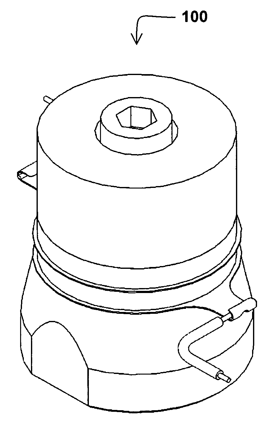
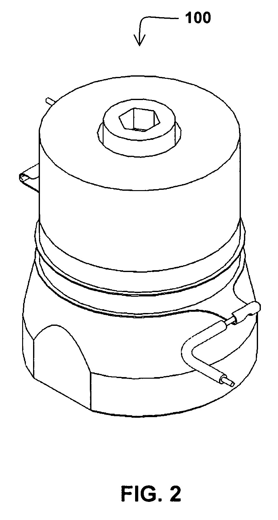
[0104]FIG. 2 shows a perspective view of one preferred embodiment of an ultrasound transducer 100 and FIG. 3 shows a top view of the transducer 100 of FIG. 2. FIGS. 4A and 4B show cross-sectional views (section H-H from FIG. 3) of the transducer 100 of FIG. 2, FIG. 4A depicting an exploded view to show the parts of the transducer 100 and FIG. 4B depicting a cross-sectional view of the transducer 100 when the transducer is under a compressed state. The transducer 100 employs a Langevin architecture, also known in the art as a sandwich transducer. According to one aspect of the invention, the transducer 100 includes a back mass 102, a front mass 104, a resonator assembly including a first ceramic disc resonator 106 and a second ceramic disc resonator 108, and a compression assembly including a central bias bolt 116. The transducer may further include an insulator, which is not shown in the drawings, disposed between the bolt 116 and the disc resonators 106 and 108, and electrodes 112 ...


PUM


Abstract

An ultrasound transducer is constructed to be under damped at higher overtone frequencies by reducing losses through one or more of the following: even pressure shaped surfaces on masses, reversed drive to at least one piezoelectric ceramic, an ultrasonically formed metallic bond between the transducer's front mass and the radiating surface, high current carrying strain relieved electrodes, fine grain structure masses, low internal friction masses and radiating materials, and zero bias stress change due to temperature variations. Improved methods and construction details for bonding the higher overtone frequency transducer to quartz are disclosed and include: front masses with cross-hatched or concentric circle patterns and invar front masses or an invar transition mass that is bonded to the quartz.

Description

CROSS REFERENCE TO RELATED APPLICATIONS [0001] This application is a continuation-in-part of, and claims priority to, commonly owned and co-pending U.S. patent application Ser. No. 11 / 115,768, filed Apr. 27, 2005 and entitled “High Power Ultrasonic Transducer,” and U.S. patent application Ser. No. 11 / 177,871, filed Jul. 8, 2005 and entitled “Low-Stress Ultrasound Transducer.” The entire contents of each of these applications is incorporated by reference herein.TECHNICAL FIELD [0002] The present invention relates to ultrasound systems, and more particularly, to systems for generating high power ultrasonics energy and introducing the ultrasonics energy into fluid media for the purpose of cleaning and / or liquid processing. BACKGROUND ART [0003] For years, ultrasonic energy has been used in manufacturing and processing plants to clean and / or otherwise process objects within liquids and to effect a process on a liquid. It is well known that objects may be efficiently cleaned by immersion...

Claims


Application Information

Patent Timeline
Patent Type & Authority Applications(United States)
IPC IPC(8): H02N2/00
CPCB06B1/0618
Inventor JOHNSON, BENJAMAN R.CAO, ZHAOXIABERNHARDT, BRIAN D.MARATHE, KAUSTUBH P.PHANEUF, GREGORY E.PUSKAS, WILLIAM L.
Owner CLEANING TECH GROUP
Why Eureka
Try Eureka