
Tire sensor device and tire information transmission method

a technology of tire information and sensor device, which is applied in the direction of fluid tightness measurement, anti-theft device, instruments, etc., can solve the problems of shortening the service life of the battery, the sensor cannot be installed at the desired location of the tire, and the tire information which can be collected is limited, so as to achieve the effect of more accurate detection

Inactive Publication Date: 2007-04-12
BRIDGESTONE CORP
View PDF7 Cites 41 Cited by
  • Summary
  • Abstract
  • Description
  • Claims
  • Application Information

AI Technical Summary

Benefits of technology

[0013] Then, it is conceivable that sensors be installed not at one location but at various locations where tire information can be easily obtained. When the above sensors are driven by a battery, a large-sized transmitter is required to transmit tire information signals to the car body side, thereby shortening the service life of the battery. Even when the above sensor device is composed of the above RF transponder, a transmitter having large transmission power for transmitting the above tire information signals to the car body side must be installed in the sensor device, whereby the device becomes bulky and power efficiency becomes low.
[0048] Further, when a predetermined sensor device is provided with means of storing power and the sensor device or the base station is provided with means of detecting the rotation angle of the sensor of the sensor device so as to detect the condition of the tire at a predetermined rotation position, the condition of the tire can be detected more accurately.

Problems solved by technology

Therefore, a plurality of sensors cannot be installed at desired locations of a tire, for example, a plurality of sensors are spaced apart from one another in the transverse direction of the tire in order to obtain information on the ground contact condition of the tire caused by lateral force.
Thus, tire information which can be collected is limited.
When the above sensors are driven by a battery, a large-sized transmitter is required to transmit tire information signals to the car body side, thereby shortening the service life of the battery.
Even when the above sensor device is composed of the above RF transponder, a transmitter having large transmission power for transmitting the above tire information signals to the car body side must be installed in the sensor device, whereby the device becomes bulky and power efficiency becomes low.

Method used


Image

  • Tire sensor device and tire information transmission method
  • Tire sensor device and tire information transmission method
  • Tire sensor device and tire information transmission method

Examples


embodiment 1

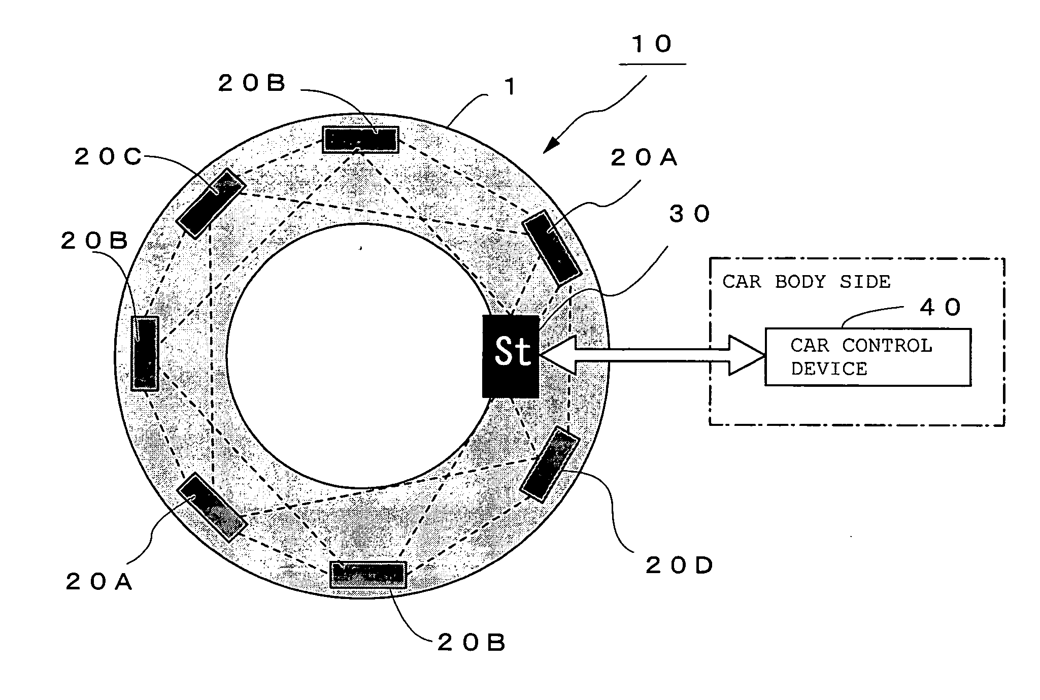
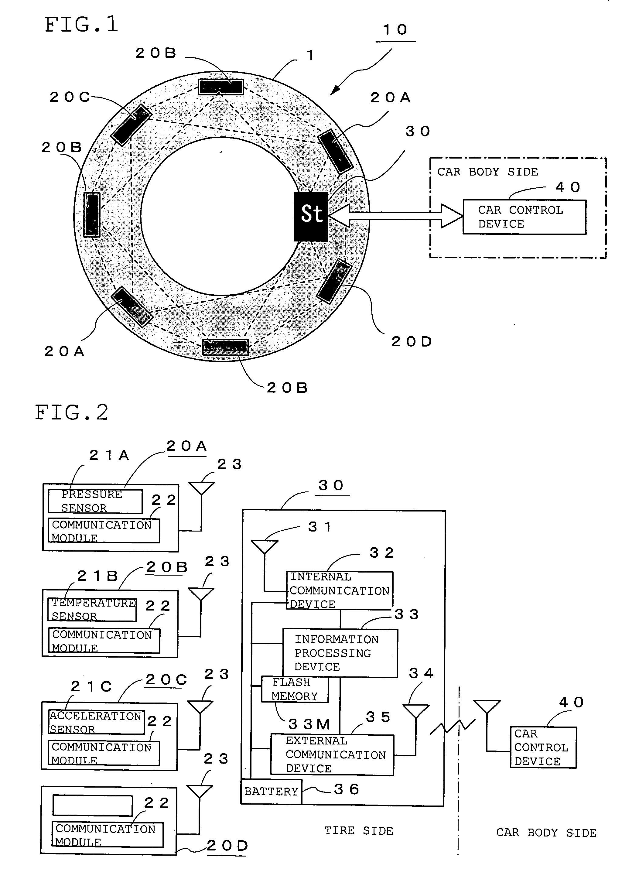
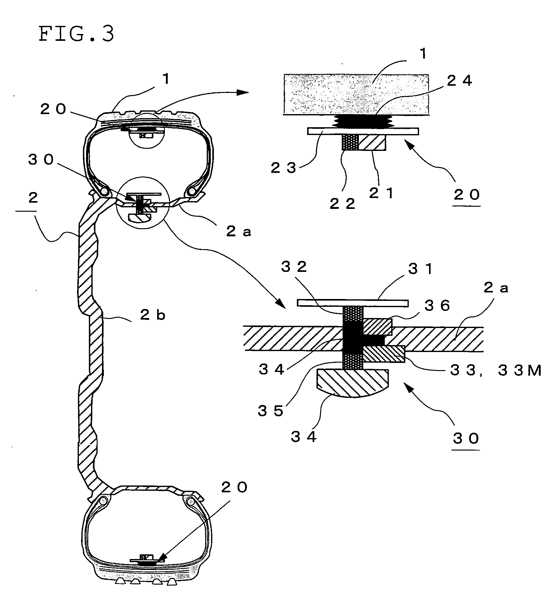
[0060]FIG. 1 is a diagram showing the outline of a tire information transmission method according to Embodiment 1 of the present invention, FIG. 2 is a functional block diagram showing the constitution of a tire sensor device, and FIG. 3 is a diagram showing the installation state of the above tire sensor device. In these figures, reference numeral 1 denotes a tire, 2 a wheel consisting of a rim 2a and a wheel disk 2b, 10 a tire sensor device comprising a plurality of sensor modules 20 (20A to 20D) installed in the tire 1 and a base station 30 for constructing an intra-tire network (to be referred to as “intra-tire LAN” hereinafter) with the sensor modules 20, processing tire information signals from the sensors 21 (21A to 21C) of the above sensor modules 20 and transmitting the signals to the car body side, and 40 a car control device installed on the car body side.

[0061] Each of the sensor modules 20 comprises a sensor and communication means corresponding to an RFID chip. More s...

embodiment 2

[0082] In the above Embodiment 1, the intra-tire network is constructed with the sensor modules 20 and the base station 30, and the sensor modules 20 are each provided with a power regenerating circuit for receiving a radio wave from the base station 30 to generate power voltage for driving the sensor 21. When power is supplied to the sensor modules from the car body side and not from the base station 30, the size and power consumption of the tire sensor device can be further reduced.

[0083]FIG. 4 is a diagram showing the outline of a tire information transmission method according to Embodiment 2, FIG. 5 is a functional block diagram showing the constitution of the tire sensor device of this embodiment, and FIG. 6 is a diagram showing the installation state of the above tire sensor device. In these figures, reference numeral 1 denotes a tire, 2 a wheel consisting of a rim 2a and a wheel disk 2b, and 50 a tire sensor device comprising a plurality of sensor modules 60 (60A to 60C) ins...


PUM


Abstract

A tire sensor device comprising sensor modules 20A to 20D, each comprising a sensor, a communication module having a communication function and a power regenerating circuit, and an antenna; and a base station comprising an internal communication device for communication with the sensor modules 20A to 20D, an information processing device for processing tire information signals from the sensor modules, an external communication device for communicating with a car control device 40 on the car body side and a power source. The sensor modules 20A to 20D and the base station 30 are arranged in the tire and constitute an intra-tire LAN. Tire information signals transmitted from the sensor modules 20A to 20D are processed by the base station 30 and transmitted to the car control device 40 so that appropriate tire information can be obtained and the size and power consumption of the sensor device can be reduced.

Description

BACKGROUND OF THE INVENTION [0001] 1. Field of the Invention [0002] The present invention relates to a tire sensor device which collects and processes information from sensors mounted in a tire and transmits the processed information to the car body side and to a tire information transmission method. [0003] 2. Description of the Prior Art [0004] Heretofore, there has been implemented a tire air pressure monitoring device which detects the inside pressure of a tire by mounting a pressure sensor device for detecting the pressure of a gas filled in the tire on a surface facing a tire cavity area of a wheel and transmits the detected information to the car body side so as to inform a driver of the inside pressure of the tire. FIG. 8(a) is a block diagram showing the constitution of a tire pressure sensor tag 80 which is the pressure sensor device of the prior art. This tire pressure sensor tag 80 comprises an air pressure sensor 81 for detecting the inside pressure of the tire, an analo...

Claims


Application Information

Patent Timeline
IPC IPC(8): B60C23/00B60C23/04
CPCB60C23/0413B60C23/0433B60C23/0483B60C23/0493B60C23/0498
Inventor ICHIKAWA, HIROMITSUHADA, HIROMASAKOKUBU, TAKAOOKU, MASAHARUTOYOFUKU, MASANOBU
Owner BRIDGESTONE CORP
Learn More