
Image scanning apparatus

Inactive Publication Date: 2007-04-12
SAMSUNG ELECTRONICS CO LTD
View PDF12 Cites 2 Cited by
  • Summary
  • Abstract
  • Description
  • Claims
  • Application Information

AI Technical Summary

Benefits of technology

[0010] An object of the present invention is to substantially solve at least the above problems and / or disadvantages and to provide additional advantages, by providing an image scanning apparatus that can be portable because of its compact size and less power consumption.

Problems solved by technology

However, image scanning apparatuses are large and requires more power consumption, thus not an ideal for used as a portable device.
In particular, a system configuration is complicated and bulkier to limit the mode of 0th-order as a separate configuration must be further included, as described in U.S. Pat. No. 6.724,515

Method used


Image

  • Image scanning apparatus
  • Image scanning apparatus
  • Image scanning apparatus

Examples


first embodiment

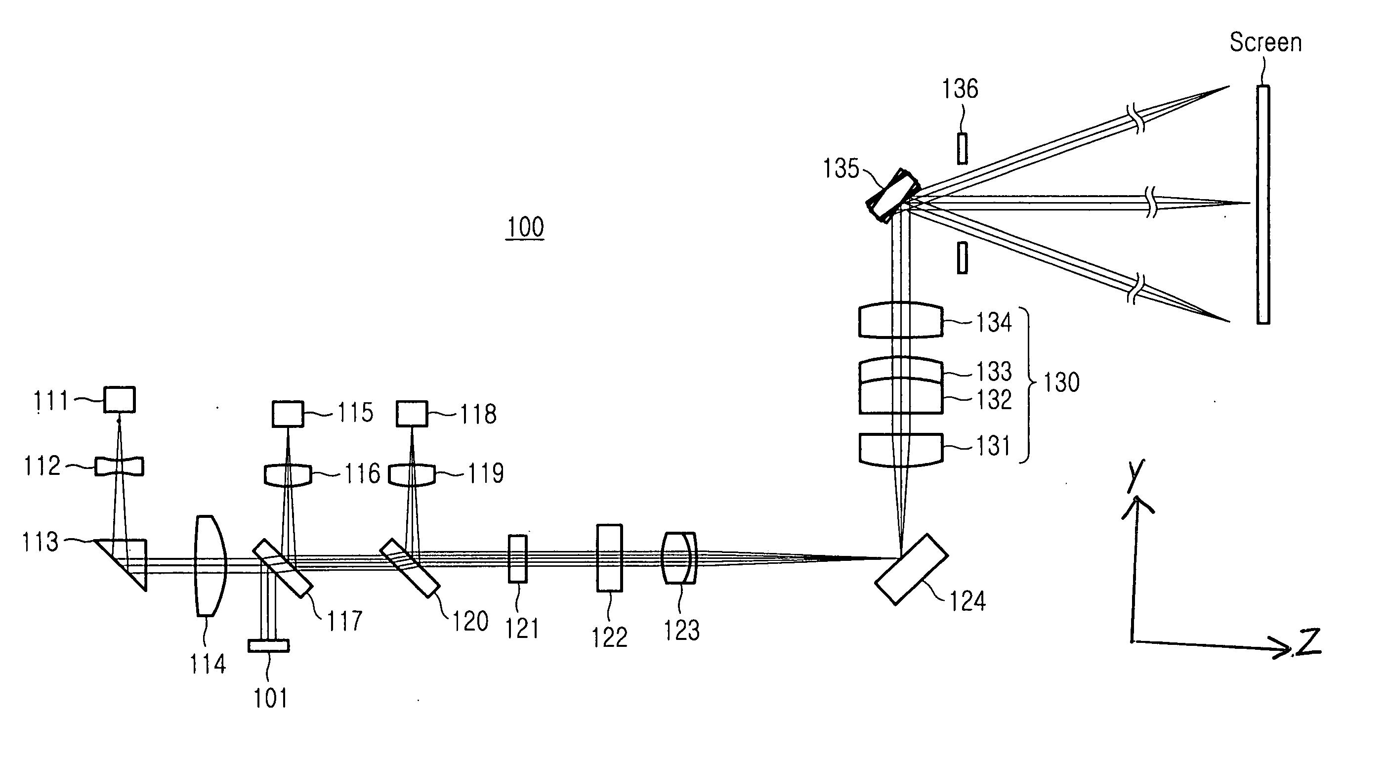
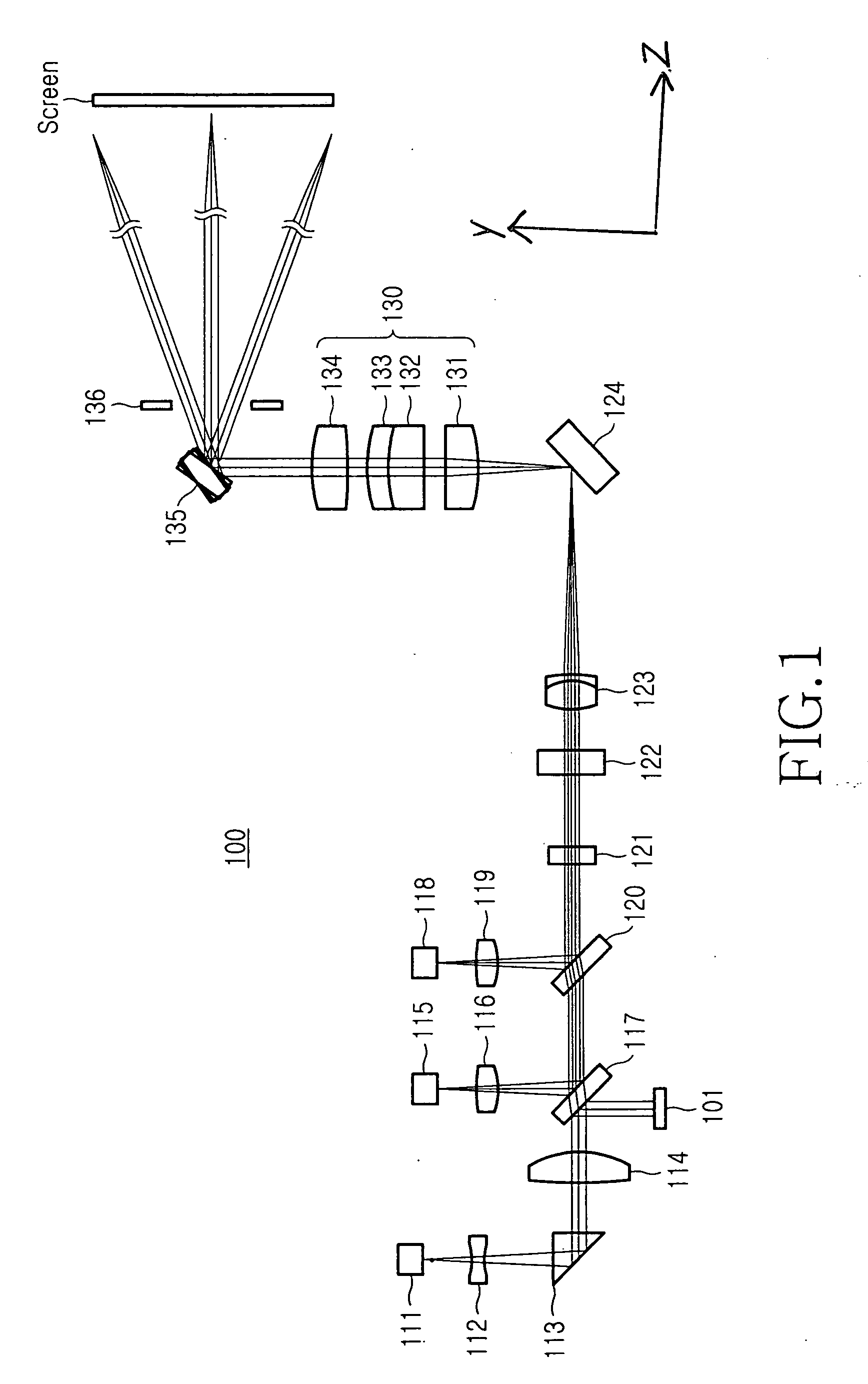
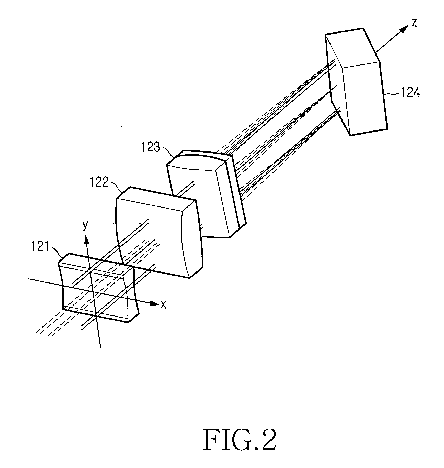
[0022]FIG. 1 is a configuration of an image scanning apparatus 100 according to the present invention. FIG. 2 is a perspective view of a portion of the configuration of FIG. 1.

[0023] Referring to FIG. 1, the image scanning apparatus 100 includes first to third light sources 111, 115, and 118 for generating light beams of different visible wavelength bands, collimation optics (114, 116, and 119) for collimating the light beams, line scan optics (121,122, and 123) for forming a stripe pattern line scan perpendicular to the traveling direction of the collimated light beams, a spatial light modulator 124, image-forming optics 130, an iris 136, a scan mirror 135, and a screen. For the first to third light sources 111, 115, and 118, a semiconductor laser or second harmonic generator (SHG), which can generate the three primary colors, i.e., green, blue, and red, can be used.

[0024] The image scanning apparatus 100 can be used as a portable compact projector. To assist the understanding of ...

second embodiment

[0043]FIG. 7 is a configuration of an image scanning apparatus 200 according to the present invention. As shown, the image scanning apparatus 200 includes first to third light sources 211, 215, and 218 for generating light beams of different visible wavelength bands, collimation optics (214, 216, and 219) for collimating the light beams, line scan optics (221, 222, and 223) for forming a stripe pattern line scan perpendicular to the traveling direction of the collimated light beams, a spatial light modulator 224, an image-forming optics 230, an iris 236, a scan mirror 235, a screen, a reflective mirror 213, first and second wavelength selection filters 217 and 220, an optical detector 201 for monitoring the magnitude of a green light beam from a portion of the green light beam, which is reflected by the first wavelength selection filter 217, and a second diffusion lens 212.

[0044] The line scan optics includes a first diffusion lens 221, a collimation lens 222, and a convergence lens...

third embodiment

[0046]FIG. 8 is a configuration of an image scanning apparatus 300 according to the present invention. As shown, the image scanning apparatus 300 includes first to third light sources 311, 315, and 318 for generating light beams of different visible wavelength bands, collimation optics (314, 316, and 319) for collimating the light beams, line scan optics (321, 322, and 323) for forming a stripe pattern line scan perpendicular to the traveling direction of the collimated light beams, a spatial light modulator 324, an image-forming optics 330, an iris 336, a scan mirror 335, a screen, first and second reflective mirrors 313 and 320 for perpendicularly changing the path of the light beams, first and second wavelength selection filters 317a and 317b, an optical detector 301 for monitoring the magnitude of a green light beam from a portion of the green light beam, which is reflected by the first wavelength selection filter 317, and a second diffusion lens 312.

[0047] The line scan optics ...


PUM


Abstract

An image scanning apparatus for realizing an image on a screen includes: a spatial light modulator module for diffracting light beams having different wavelengths into relevant modes; and an iris for limiting light beams of modes except a mode of 0th-order among the modes diffracted by the spatial light modulator module.

Description

CLAIM OF PRIORITY [0001] This application claims priority under 35 U.S.C. § 119 to an application entitled “Image Scanning Apparatus,” filed in the Korean Intellectual Property Office on Oct. 10, 2005 and assigned Ser. No. 2005-95072, the contents of which are incorporated herein by reference. BACKGROUND OF THE INVENTION [0002] 1. Field of the Invention [0003] The present invention relates generally to an image scanning apparatus, and in particular, to a portable image scanning apparatus including a spatial modulator module. [0004] 2. Description of the Related Art [0005] Recently, image scanning apparatuses using a laser light source, such as a semiconductor laser, have been suggested. Such an image scanning apparatus having a laser light source can be used in projectors, projector televisions, color scanners, and color printers. When the image scanning apparatus including a laser light source is used in projectors and projector televisions, the image scanning apparatus obtains an ...

Claims


Application Information

Patent Timeline
IPC IPC(8): G02B26/08
CPCG02B26/101G02B26/106G02B27/1006G02B27/102G02B27/104G02B27/108G02B27/1086G02B27/145G02B27/42G02B27/4227G02B26/10
Inventor PARK, MUN-KUELEE, JUNG-KEEPARK, SUNG-SOOPARK, BYEONG-HOON
Owner SAMSUNG ELECTRONICS CO LTD
Features
  • Generate Ideas
  • Intellectual Property
  • Life Sciences
  • Materials
  • Tech Scout
  • Unparalleled Data Quality
  • Higher Quality Content
  • 60% Fewer Hallucinations
Learn More