
Boring tool with coolant hole

a technology of coolant hole and tool, which is applied in the direction of boring bars, shaping cutters, manufacturing tools, etc., can solve the problems of large slope angle of spray opening relative to the axial center of the shank, etc., and achieve the effect of reducing damage to the cut surfa

Inactive Publication Date: 2007-04-12
SUMITOMO ELECTRIC HARDMETAL CORP
View PDF4 Cites 24 Cited by
  • Summary
  • Abstract
  • Description
  • Claims
  • Application Information

AI Technical Summary

Benefits of technology

The present invention aims to prevent chips from entering narrow spaces between a shank and a workpiece and minimize damage to the cut surface. This is achieved by positioning the spray opening of a coolant hole on the shank of a boring tool offset from the shank center towards the cutting edge, with a slope angle of up to 10 degrees, and a distance from the cutting edge of the cutting tool up to 3 times the shank diameter. The spray opening is designed to direct coolant towards the tip of the shank, where it flows with the coolant and encounters flow restrictions imposed by the workpiece, resulting in the chips being blown away and ejected outside through the workpiece hole without causing abrasion of the cut surface.

Problems solved by technology

This may lead to damage to the cut surface (finishing surface) 22 of the workpiece 20.
This leads to the problem described above because, for structural reasons, the main hole 2a of the coolant hole 2 is provided at the center of the shank 1, resulting in a large slope angle for the spray opening relative to the axial center of the shank.

Method used


Image

  • Boring tool with coolant hole
  • Boring tool with coolant hole
  • Boring tool with coolant hole

Examples


first example

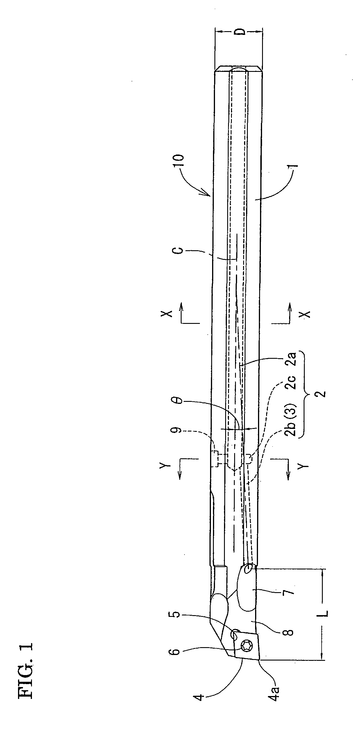
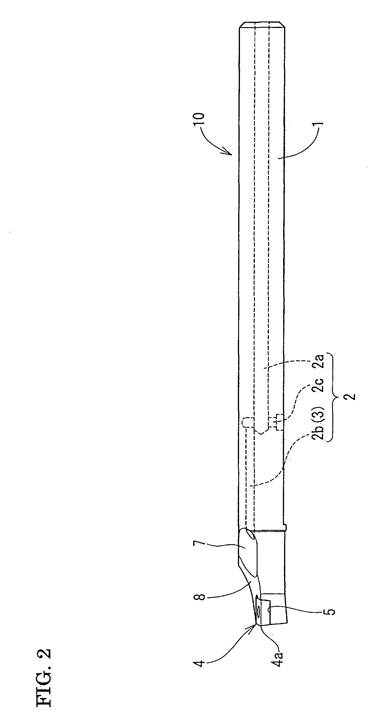
[0040] In tests, samples 1-6 were formed with different slope angles θ for the spray opening of the coolant hole relative to the axial center of the shank and different lengths L from the cutting edge of the cutting tool to the spray opening, these variations being within their respective valid ranges. In comparative samples 1-3, the slope angle θ of the spray opening and / or the distance L from the cutting edge to the spray opening were outside the valid range. The different aspects of the boring tools used are shown in Table 1.

[0041] The cutting conditions were as shown below. These are standard cutting condition used for inner diameter finishing.

[0042] Tool used: steel tool with a shank diameter of 12 mm (ISO model number S16M-SCLCR0602-14) with coolant hole added.

[0043] Cutting tool: diamond-shaped finishing insert with replaceable cutting edge, chip breaker for finishing, and a corner angle of 80 deg (ISO model number CCMT060204N).

[0044] Workpiece: SCr420 JIS, hole diameter ...


PUM

PropertyMeasurementUnit
slope angleaaaaaaaaaa
pressureaaaaaaaaaa

Abstract

In a boring tool with a coolant hole, a spray opening of a coolant hole formed in a shank is positioned with a radial offset from the shank center toward the side on which a cutting tool is formed. The spray opening is sloped at an angle of 0 to 10 deg from an axial center of the shank toward a cutting edge. Also, the spray opening is positioned so that a distance from the cutting edge to the opening is up to three times the shank diameter.

Description

INCORPORATION BY REFERENCE [0001] The present application claims priority under 35 U.S.C. §119 to Japanese Patent Application No. 2005-265371 filed Sep. 13, 2005. The content of the application is incorporated herein by reference in its entirety. BACKGROUND OF THE INVENTION [0002] 1. Field of the Invention [0003] The present invention relates to a boring tool with coolant hole for machining the inner diameter of a hole. More specifically, the present invention relates to a boring tool with coolant hole with a feature for spraying a cut section with a coolant. The coolant referred to in the present invention is not restricted to fluid. It also covers vapors containing lubricant used in minimum quantity lubricant (MQL) cutting. [0004] 2. Description of the Background Art [0005] Examples of conventional technologies for boring tools with coolant holes include Japanese Laid-Open Patent Publication Number 2003-71608 and Japanese Laid-Open Patent Publication Number 2005-81459. [0006] In t...

Claims


Application Information

Patent Timeline
Patent Type & Authority Applications(United States)
IPC IPC(8): B23P15/28
CPCB23B27/007Y10T407/14B23B29/02B23B27/10
Inventor MURAKAMI, DAISUKEUEDA, MASANOBU
Owner SUMITOMO ELECTRIC HARDMETAL CORP
Learn More