Discontinuous conveyor system

a conveyor system and conveyor belt technology, applied in the direction of thin material processing, electrical equipment, article separation, etc., can solve the problems of increasing the cost and complexity of the container transfer system, reducing the throughput of the container in the fab, and reducing the efficiency of the tool loading interface, so as to simplify the tool loading interface

Inactive Publication Date: 2007-04-12
MURATA MASCH LTD
View PDF10 Cites 29 Cited by
  • Summary
  • Abstract
  • Description
  • Claims
  • Application Information

AI Technical Summary

Benefits of technology

[0008] One aspect of the present invention is to provide a material transport system that simplifies the tool loading interface between a tool bay and, for example, a conveyor. In general, the conveyor system eliminates the need for separate lift and translate mechanisms typically required for loading/unloading FOUPs from the conveyor to a shelf and moving the FOUP from the shelf to a processing tool. In one em

Problems solved by technology

However, transferring FOUPs from the conveyor to a tool load port currently requires multiple mechanisms.
These mechanisms reduce container throughput in the fab as well as add cost and complexity to the container transfer system.
If this happens, traffic on t

Method used


Image

  • Discontinuous conveyor system
  • Discontinuous conveyor system
  • Discontinuous conveyor system

Examples


Embodiment Construction

[0019] The embodiments of this invention are described and illustrated as moving FOUPs throughout a semiconductor fabrication facility. However, the present invention is not limited to FOUPs and / or semiconductor manufacturing. For purposes of describing this invention, A FOUP generally represents, by way of example only, wafer containers (with walls and without), cassettes, flat panel displays, Standard Mechanical Interface (SMIF) pods, or any substrate structure for supporting a substrate, whether the structure supports a single substrate or multiple substrates.

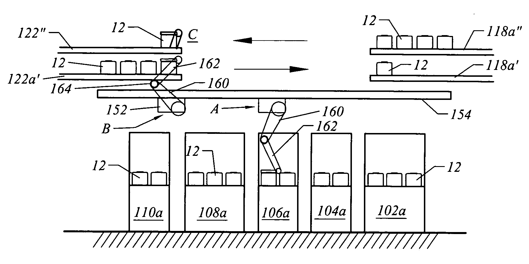
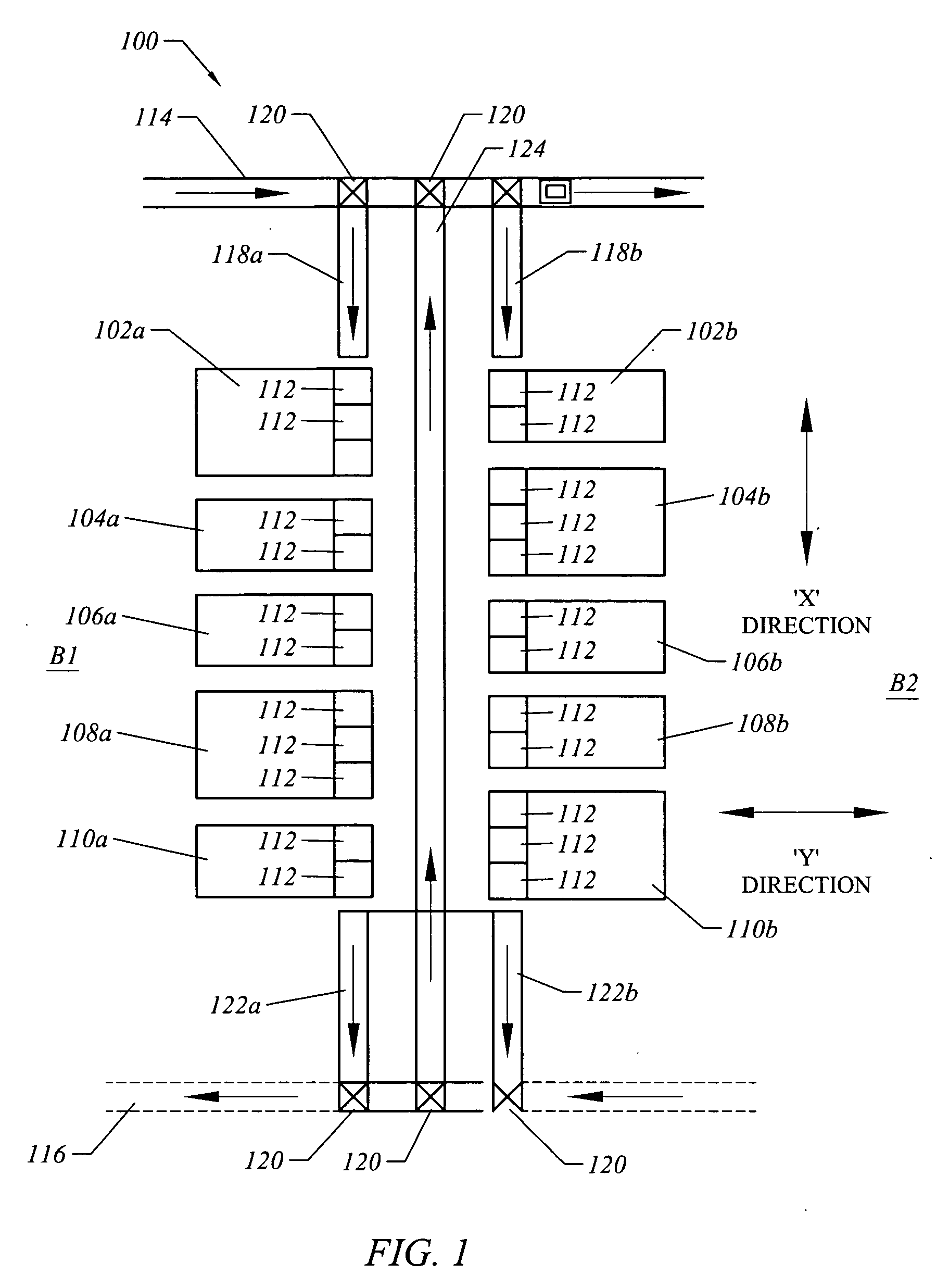
[0020]FIG. 1 illustrates one embodiment of a material transport system 100 according to the present invention. In this embodiment, an interbay conveyor 114 delivers FOUPs 12 bewteen two bays B1 and B2. Each tool bay includes multiple processing tools 102. For example, as shown in FIG. 1, tool bay B1 includes processing tools 102a, 104a, 106a, 108a and 110a, and tool bay B2 includes processing tools 102b, 104b, 106b, 108b an...


PUM


Abstract

The present invention generally comprises a transport system for transporting containers throughout a fabrication facility, and more specifically through a tool bay in the fabrication facility. The present invention generally includes a first container transport system for transporting a container from an interbay conveyor towards the first tool bay, a second container transport system for moving a container away from the first tool bay and a tool loading device to move containers between the first and second container transport systems and a load port. A merged return conveyor for transporting a container between the second container transport system and the interbay conveyor may also be included.

Description

FIELD OF THE INVENTION [0001] The present invention generally relates to a container delivery system. More specifically, the present invention comprises an intrabay conveyor system having a container delivery device for moving containers between a first material transport system, a second material transport system and a load port of a processing tool. BACKGROUND OF THE INVENTION [0002] Manufacturing of semiconductor devices typically involves performing a sequence of procedures with respect to a substrate, such as silicon substrate, glass plate, etc. These steps may include polishing, deposition, etching, photolithography, heat treatment, and so forth. It is generally the case that other processes are required to be performed at other processing locations within a fabrication facility, and it is therefore necessary to transport the substrates within the fabrication facility from one processing location to another. Depending upon the type of semiconductor device to be manufactured, t...

Claims


Application Information

Patent Timeline
IPC IPC(8): H01L21/677
CPCH01L21/67727H01L21/6773H01L21/67733H01L21/67736H01L21/67769H01L21/67775
Inventor BONORA, ANTHONY C.ROGERS, TED
Owner MURATA MASCH LTD
Why Eureka
Try Eureka