Coating material supply installation and associated operating procedure

a technology of coating material and supply device, which is applied in the direction of liquid handling, application, packaging goods type, etc., can solve the problems of piston meter having to be filled, slowing down the painting process, and affecting the appearance of the finished product, so as to reduce the color change time, reduce the amount of paint flow, and reduce the effect of color change tim

Active Publication Date: 2007-04-12
DURR SYST INC
View PDF18 Cites 18 Cited by
  • Summary
  • Abstract
  • Description
  • Claims
  • Application Information

AI Technical Summary

Benefits of technology

[0005] According to teachings of the invention herein, the coating means meter (e.g., a piston meter) is not filled directly from the color changer but indirectly through an interposed coating means reservoir. This provides the opportunity to fill the coating means reservoir with coating means while painting is in progress and not during the times for color changes, which contributes to reducing the color change times. The continuous charging of the coating means reservoir while painting is in progress also provides the advantage that, because of the time available for charging, relatively small paint flow quantities in the supply lines (e.g., color circulation lines and special color supply) are adequate so that the appropriate lines can have a smaller line cross-section, thereby reducing installation costs.

Problems solved by technology

There are disadvantages to this known painting robot.
These disadvantages include the relatively long duration of the color change, which results in a slowing down of the painting process particularly with frequent color changes.
These disadvantages also include the fact that the piston meter has to be filled again, even without a color change, when the entire charge capacity of the piston metering pump has been applied by the rotational atomizer.
The recharging of the piston meter by the color changer is similarly relatively time-consuming, which slows down the painting process.

Method used


Image

  • Coating material supply installation and associated operating procedure
  • Coating material supply installation and associated operating procedure
  • Coating material supply installation and associated operating procedure

Examples


Embodiment Construction

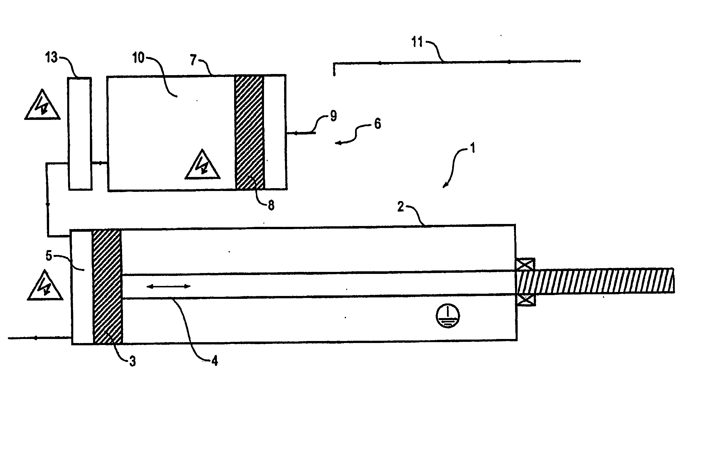
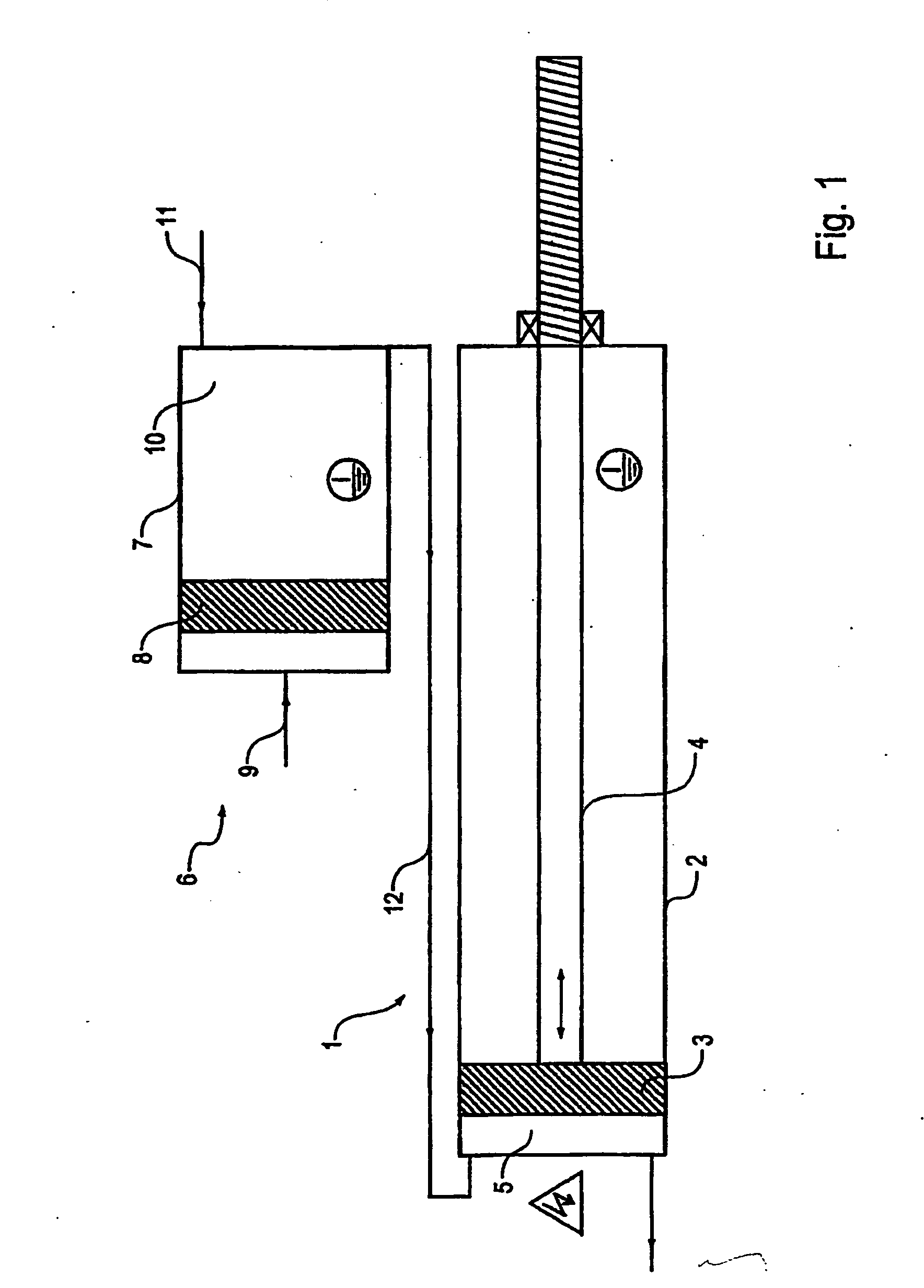
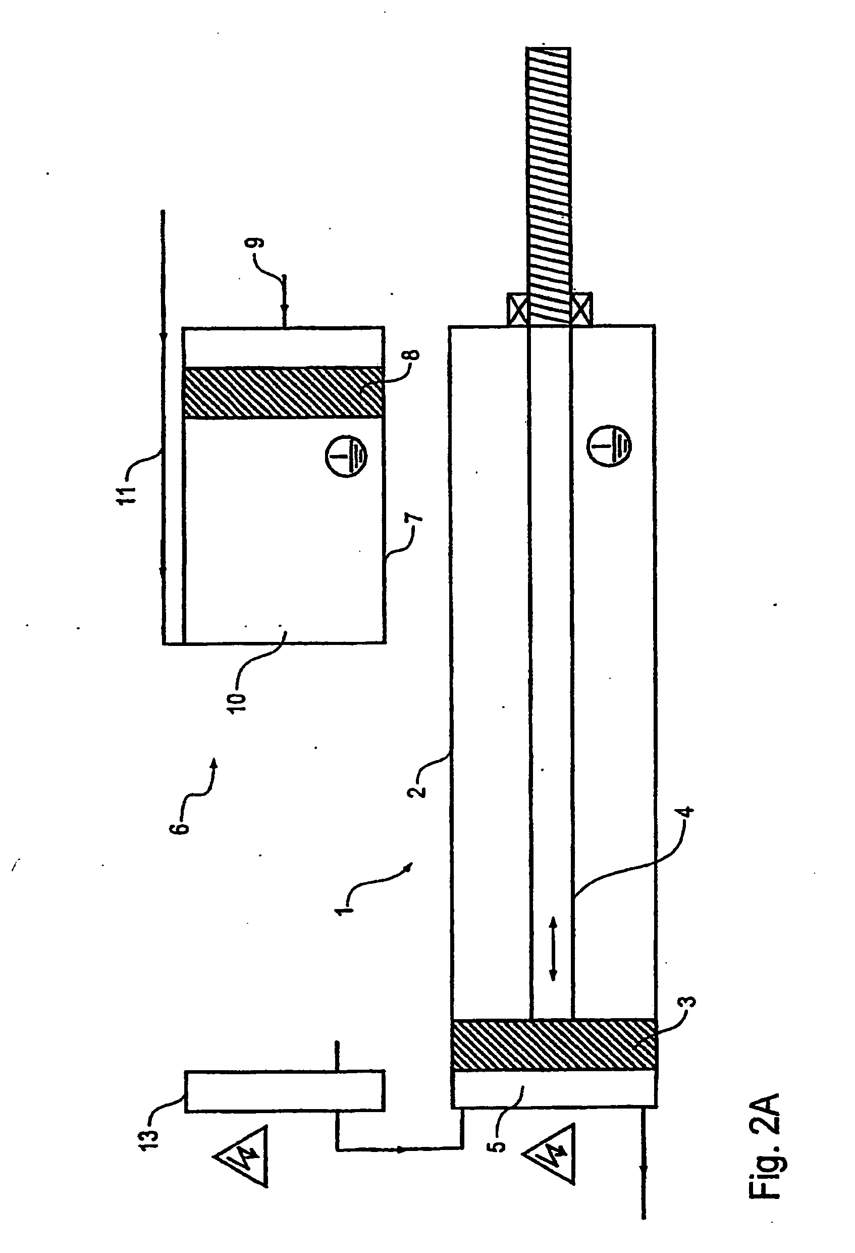
[0027] In what follows, the embodiment of a coating means supply device shown in FIG. 1 will be described first. This coasting supply means supply device can, for example, be located on a robot arm of a painting robot. A painting robot with a conventional coating means supply device so placed is known within the art (see, for instance, publication WO 2004 / 037436 mentioned above). Therefore the construction and the operation of the painting robot with a conventional coating means supply device and of the other components will not be repeated here.

[0028] The coating means supply device shown in FIG. 1 has a coating means meter 1, which in FIG. 1 is a piston meter. The coating means meter 1 has a cylinder 2 and metering piston 3 moveable in the direction of the arrow. The metering piston 3 is driven mechanically by a piston rod 4, which in turn can be driven by an electric motor, pneumatically or hydraulically. In the cylinder 2 of the coating means meter 1 there is a metering chamber...


PUM

PropertyMeasurementUnit
pressureaaaaaaaaaa
pressureaaaaaaaaaa
voltage potentialaaaaaaaaaa

Abstract

A coating means supply device, in particular for a paint facility, having a coating means meter that meters coating means to be applied to application equipment. The coating means supply device includes a coating means reservoir for holding the coating means and for supplying the coating means meter with the coating means. During application of coating material to equipment, the coating means reservoir is at ground potential and is located upstream from the coating means meter, which is at high-voltage potential. The reservoir is connected via an insulating path to the coating means meter. The coating means meter is at ground potential when the coating means reservoir supplies coating means to the coating means meter. Before the coating means meter is returned to a high-voltage potential for continued application of coating material, the insulating path is emptied to again insulate the coating means meter from the coating means reservoir.

Description

RELATED APPLICATION [0001] This application claims priority to U.S. Provisional patent Application Ser. No. 60 / 791,164 filed Apr. 11, 2006, which application is incorporated herein in its entirety by reference. This application also claims priority to German application no. 10 2005 048 223.6 filed Oct. 7, 2005, no. 10 2005 060 959.7 filed Dec. 20, 2005 and no. 20 2005 019 876.5 filed Dec. 20, 2005, each of which is also incorporated in its entirety by reference.FIELD OF THE INVENTION [0002] The present invention relates to a coating means supply device and an associated operating method for the same. BACKGROUND [0003] Multi-axis painting robots with a rotational atomizer as the application equipment can be used, for example, for painting automobile body parts. Such robots are known in the art (see, for example, World Intellectual Property Organization publication WO 2004 / 0374 36 A1). A piston meter, which supplies paint to a rotational atomizer, is mounted on the arm of the painting...

Claims


Application Information

Patent Timeline
Patent Type & Authority Applications(United States)
IPC IPC(8): B05D1/04B05B5/025
CPCB05B5/1625B05B5/1675B05B12/14
Inventor BAUMANN, MICHAELHERRE, FRANKMARTIN, HERBERTMELCHER, RAINERMICHELFELDER, MANFREDSEIZ, BERNHARDOSTIN, RICHARDHELDT, ROBERT F.
Owner DURR SYST INC
Why Eureka
Try Eureka