Jet-propelled watercraft

a technology of watercraft and propeller, which is applied in the direction of marine propulsion, special-purpose vessels, vessel construction, etc., can solve the problems of complicated control unit to control such operations and the constant operation of the throttle valv

a technology of watercraft and propeller, which is applied in the direction of marine propulsion, special-purpose vessels, vessel construction, etc., can solve the problems of complicated control unit to control such operations and the constant operation of the throttle valv

US20070082568A1Inactive Publication Date: 2007-04-12HONDA MOTOR CO LTD

Image

  • Jet-propelled watercraft
  • Jet-propelled watercraft
  • Jet-propelled watercraft

Examples


Embodiment Construction

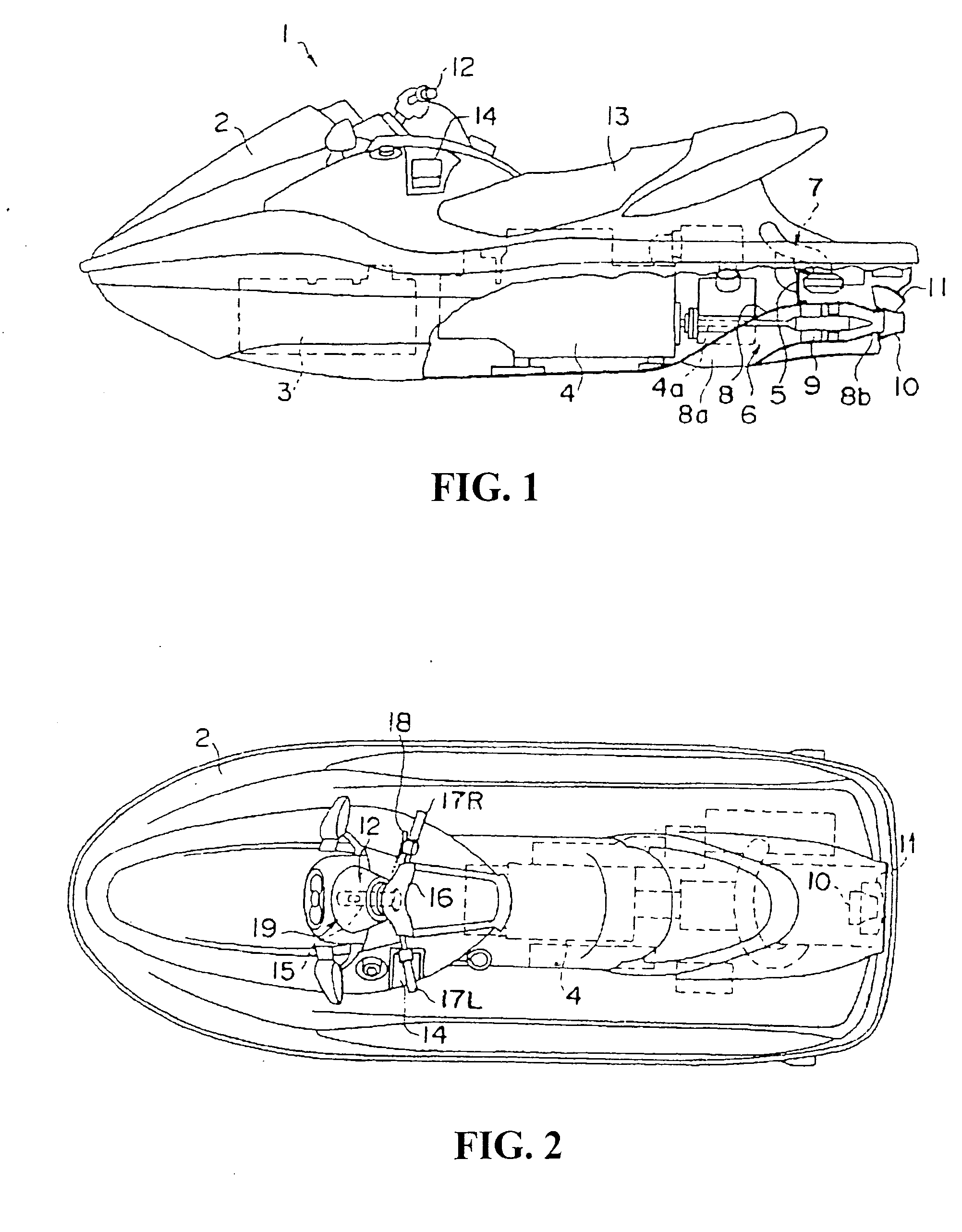
[0025] A preferred embodiment of the present invention will be described in the following with reference to the accompanying drawings. First, an overall configuration of a jet-propelled watercraft according to the present embodiment will be described with reference to FIGS. 1 and 2. A jet-propelled watercraft 1 includes a hull 2 and the following parts provided inside the hull 2: a fuel tank 3 disposed in a front area, an engine 4 disposed rearward of the fuel tank 3, a pump room 5 disposed rearward of the engine 4, a jet propeller 6 provided in the pump room 5, and an exhaust unit 7 with an intake side attached to the engine 4 and an exhaust side attached to the pump room 5. There are a steering mechanism 12 provided upward of the engine 4 and a seat 13 provided rearward of the steering mechanism 12 and above the hull 2. A rider to drive the jet-propelled watercraft 1 straddles the seat 13 and operates the steering mechanism 12.

[0026] The jet propeller 6 is communicated with a wat...


PUM


Abstract

A jet-propelled watercraft capable of maintaining a propulsion force required for a turn made at the same time as closing of a throttle valve. The jet-propelled watercraft has an auxiliary intake valve and an ECU. The auxiliary intake valve in an intake pipe opens / closes an auxiliary intake passage to bypass a throttle valve. The ECU performs control such that an opening of the auxiliary intake valve in a state where the rotation speed of the engine is not lower than a threshold value is larger than the opening of the auxiliary intake valve in a state where the engine is idling. When in a state where the rotation speed is not lower than the threshold value, it is detected that the throttle valve is completely closed and that a steering mechanism has been turned by a prescribed angle or more, a current opening of the auxiliary intake valve is maintained.

Description

CROSS-REFERENCE TO RELATED APPLICATION [0001] The present application claims priority under 35 U.S.C. §119 to Japanese Patent Application No. 2005-278296, filed Sep. 26, 2005, the entire contents of which are hereby incorporated by reference. BACKGROUND OF THE INVENTION [0002] 1 Field of the Invention [0003] The present invention relates to a jet-propelled watercraft which obtains a propulsion force by discharging a water jet from a nozzle and which can turn its hull by swinging the nozzle to the left and right. [0004] 2 Description of Background Art [0005] A jet-propelled watercraft is configured to obtain a propulsion force by discharging a water jet and change the direction of its hull by changing the direction of the water jet. It cannot change its direction when no water jet is discharged. When a rider driving such a jet-propelled watercraft gets around an obstacle, he or she tends to slow down the watercraft and, at the same time, change the direction of the watercraft by turn...

Claims


Application Information

Patent Timeline
12 Apr 2007
Publication
US20070082568A1
IPC
F02B61/04
CPC
F02M23/06; Y02T10/146; Y02T10/12
Inventors
URAKI, MAMORU; SUGIYAMA, HIDEKI