
Rapid cooling and heating of car seats with massaging effects

a technology of massaging effect and car seat, which is applied in the direction of heating apparatus, seating, knitting, etc., can solve the problems of heat and moisture accumulation at the contact surface, interfering with blood perfusion and circulation, and causing considerable discomfort and driver fatigue, so as to reduce fatigue, enhance blood circulation, and maintain skin temperature

Active Publication Date: 2007-04-19
KOLON GLOTECH INC +1
View PDF1 Cites 35 Cited by
  • Summary
  • Abstract
  • Description
  • Claims
  • Application Information

AI Technical Summary

Benefits of technology

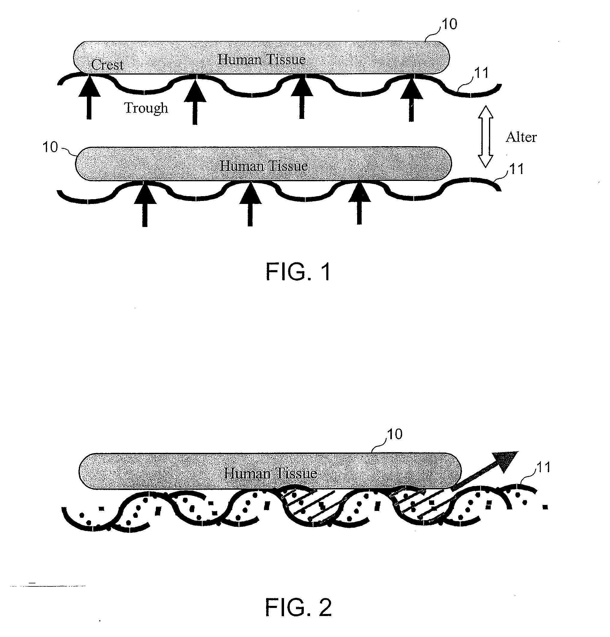
[0080] The invention provides an active seat surface that creates wave motion. The wave motion is created using straps of fabric laid on the seat surface. The wave motion on the seat surface alters the pressure distribution on the driver and removes heat and moisture at the contacting surface.
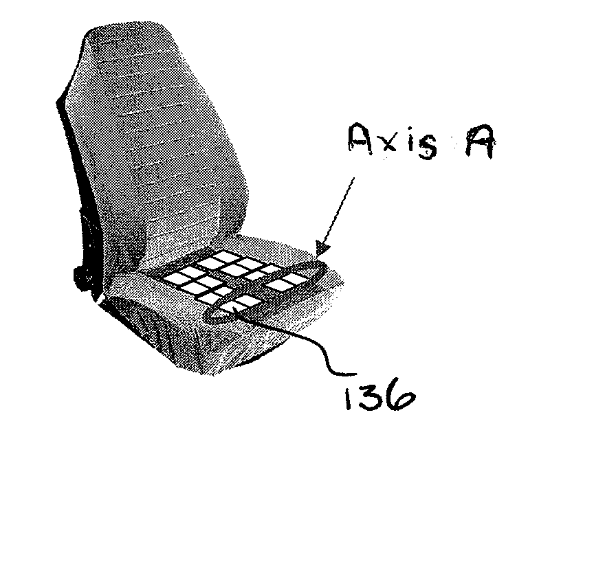
[0086] The invention also provides a lifting and sinking apparatus and method for a seat. Multiple lifting motions are created sequentially to alter the pressure distribution on the tissue and remove heat and moisture at the contacting surface. The lifting and sinking motions are also created by straps laid under the fabric of the seat. Pulling of the fabric reduces the length of the strap and thereby lifts the strap creating pressure on the body. In order to create this motion, side panels to hold the edges of the strap are used. These change the direction of the force or displacement from lateral to vertical. The sinking motion is created by pulling down certain points of the seat. The sinking motion creates crater-like depressurized zones that enhance the blood circulation and enhance ventilation at the sinking points.
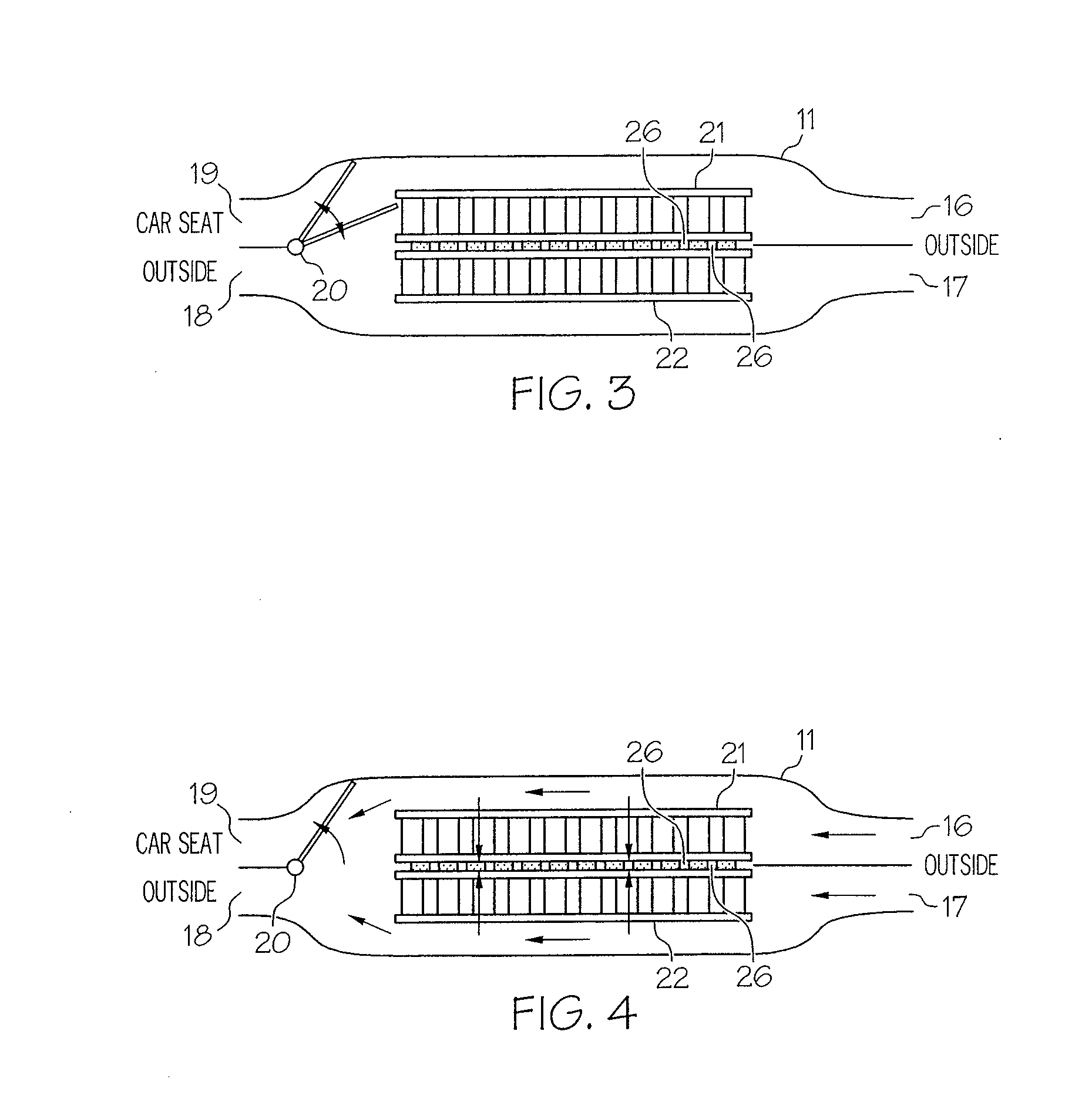
[0087] In accordance with the invention, auxiliary motion in the seat is also created. The displacement of the SMA wires is further used for auxiliary motions of the side flaps for a car backrest. The side flaps can be used to cradle the body better, especially during turning. The side flaps are actuated by transmitting the motion of SMA actuator units from the actuator box, which is placed under the car seat. The issue of limited displacement of SMA actuators is overcome in the invention by using a ratcheting mechanism. The position of the side flaps is controlled in small discrete steps, thereby eliminating the need to control the position of the individual SMA actuator units. A routing scheme, using Kevlar wires and cable housing, from the actuator box to the point of actuation is also used.
[0109] Hence, the invention is directed to a new approach to car seat design for alleviating long-drive fatigue. To enhance blood circulation as well as to keep the skin temperature and moisture at desired levels, an active control of the seat surface is accomplished with the use of Shape Memory Alloy (SMA) wire actuators. Since SMA actuators have high power-to-weight ratio, a multitude of SMA actuators can be embedded in a limited space.

Problems solved by technology

Long hours of driving cause the driver's tissue at the thighs and hips to be pressurized for an extended period and result in considerable discomfort and driver fatigue.
Capillary blood vessels may collapse under a pressure higher than 30 mmHg thereby interfering with blood perfusion and circulation when the driver is seated for a long time.
Furthermore, continuous contact with the seat surface often causes heat and moisture accumulation at the contact surface.
A driver who is driving for an extended period of time can be fatigued due to inadequate blood perfusion at the tissue under persistent pressure.
However, the massage effect should not interfere with driving and, therefore, conventional massage is not generally applicable to driving an automobile.
But these fast vibrations could cause itchiness and other discomfort when applied for a long time.
These may interfere with driving, and are therefore not applicable to driver car seats.
Bulky motors and mechanisms also make them unfavorable for car seat applications.
They are effective for redistributing pressure, but no sophisticated motion can be created.

Method used


Image

  • Rapid cooling and heating of car seats with massaging effects
  • Rapid cooling and heating of car seats with massaging effects
  • Rapid cooling and heating of car seats with massaging effects

Examples


Embodiment Construction

[0152]FIG. 1 contains a schematic diagram of an active seat surface 11 for altering pressure distribution on a person in accordance with an embodiment of the invention. As illustrated in the figure, the body of the user, illustrated by human tissue 10, is supported at different areas of contact, so that the pressurized tissue areas may be changed. The figure shows a wave pattern of crests and troughs that are altered periodically. Referring to the “before” and “after” views, the motion of the wave pattern of crests and troughs is observed.

[0153]FIG. 2 contains a schematic diagram of the active seat surface 11 of the invention shown in FIG. 1, illustrating propagating surface waves for removing hot, humid air. To remove heat and moisture at the contact area, the air gap between the crest and the trough is relatively large. Furthermore, if the wave propagates, as shown in FIG. 2, the air of high moisture and temperature that is captured between the human skin and the trough may be tr...


PUM

PropertyMeasurementUnit
Temperatureaaaaaaaaaa
Lengthaaaaaaaaaa
Pressureaaaaaaaaaa

Abstract

An apparatus and method for providing controlled heating, cooling and motion, in a device such as an active robotic automobile seat, are disclosed. A shape memory alloy (SMA) element, which changes shape upon application of a temperature change to the SMA element, is coupled to a thermoelectric device. Heat flows through the TED upon application of an electrical current through the TED. The apparatus is operable in one of a plurality of modes. In a first mode, a current is applied through the TED to cause a temperature change in the SMA element to change the shape of the SMA element. In a second mode, a current is applied to the TED to cause heat flow in a space adjacent to the apparatus. By controlling application of current to the TED, controlled motion, heating and cooling are achieved in the seat.

Description

RELATED APPLICATION [0001] This application is based on U.S. provisional application Ser. No. 60 / 819,083, filed on Jul. 7, 2006 and is a continuation-in-part of U.S. application Ser. No. 11 / 116,002, filed on Apr. 27, 2005, which is based on U.S. provisional application Ser. No. 60 / 565,894, filed on Apr. 28, 2004, the contents of which are incorporated herein in their entirety by reference.BACKGROUND OF THE INVENTION [0002] Long hours of driving cause the driver's tissue at the thighs and hips to be pressurized for an extended period and result in considerable discomfort and driver fatigue. Capillary blood vessels may collapse under a pressure higher than 30 mmHg thereby interfering with blood perfusion and circulation when the driver is seated for a long time. Furthermore, continuous contact with the seat surface often causes heat and moisture accumulation at the contact surface. Periodically stimulating the tissue in contact with the car seat, as well as providing adequate ventilat...

Claims


Application Information

Patent Timeline
IPC IPC(8): F25B21/02A47C31/00
CPCA61H2201/0138A61H2201/0149A61H2201/0207A61H2201/0214A61H2201/025A61H2201/0264A61H2201/0285A61H2201/5007A61H2205/10B60N2/448B60N2/5635B60N2/5678D04B21/04F25B21/04B60N2/976D03D11/00B60N2/58D03D15/283D03D15/44D03D15/43D01D5/32D01D10/02D10B2331/04D10B2331/02D10B2321/08D10B2101/20D10B2101/12D10B2505/12
Inventor ASADA, H. HARRYMENON, MANAS C.
Owner KOLON GLOTECH INC
Learn More