Suction roll in a machine for producing a fibrous web

a technology of suction roll and fibrous web, which is applied in the direction of drying machine, press section, light and heating apparatus, etc., can solve the problems of insufficient removal of boundary air layer between paper web and roll or fabric which rests on it, difficulty in transfer of paper web, and inability to quickly remove boundary air layer or fabric, etc., to achieve the effect of reliably transferring over the web width

Inactive Publication Date: 2007-04-19
VOITH PATENT GMBH
View PDF4 Cites 16 Cited by
  • Summary
  • Abstract
  • Description
  • Claims
  • Application Information

AI Technical Summary

Benefits of technology

[0024] Overall, the advantages of the invention consist in the fact that the suction roll has a plurality of regions over its width or its circumference, in which the boundary air between the paper of the fibrous web and the fabric or the roll can be removed rapidly on account of the great open surface and therefore the web as a whole can be held and transferred reliably over the web width.

Problems solved by technology

Suction rolls of this type have the disadvantage that the boundary air layer which is formed between the paper web and the roll or the fabric which rests on it is not removed rapidly enough when a paper web is transferred over its full web width.
Difficulties can also occur during the transfer of paper webs.
If, as an alternative, the proportion of the open surface area to the overall surface area of the circumferential surface of the suction roll were increased, the air amounts to be removed by suction would be too great.

Method used


Image

  • Suction roll in a machine for producing a fibrous web
  • Suction roll in a machine for producing a fibrous web
  • Suction roll in a machine for producing a fibrous web

Examples


Embodiment Construction

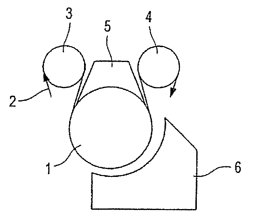
[0031] Referring now to the drawings, and more particularly to FIG. 1, there is shown a suction roll 1 is arranged behind a pressing section of a machine for producing a fibrous web 2, at the inlet of a drying section. A fibrous web 2 is guided over a first deflection roll 3 together with a dryer fabric, downward around the cover of the suction roll 1, and is guided further upward over a further deflection roll 4. A stabilizer 5 is positioned between the deflection rolls 3, 4 above the suction roll 1, which stabilizer 5 supplies the required vacuum, in order that the suction roll 1 can suck the fibrous web 2 onto its circumferential surface through the dryer fabric.

[0032] An impingement dryer 6 which covers substantially the outlet-side (as viewed in the web running direction) lower quadrant of the suction roll 1 and dries the fibrous web 2 is arranged on the underside of the suction roll 1.

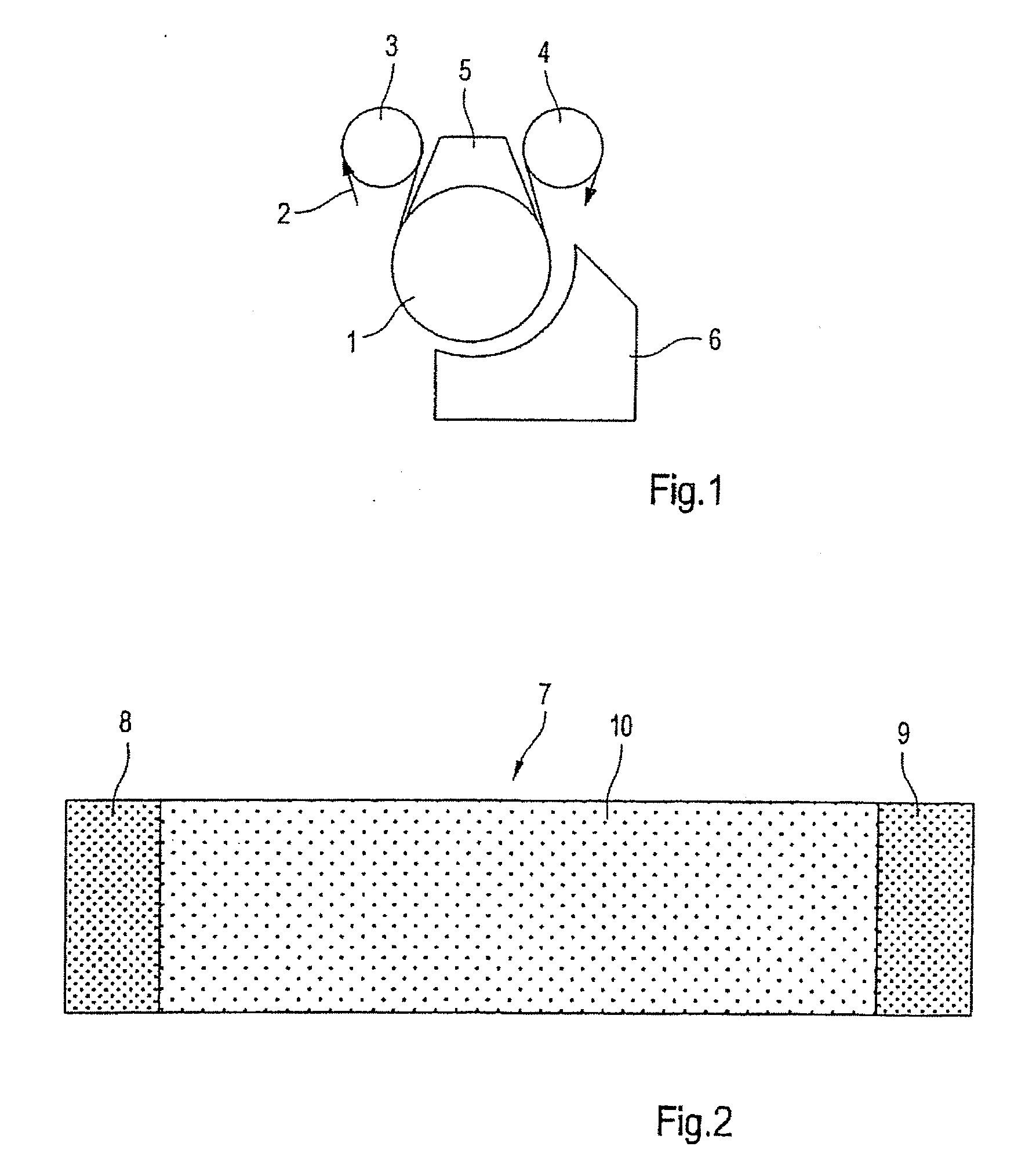
[0033] In one embodiment of the present invention, the suction roll 1 (FIG. 2) has at the e...


PUM


Abstract

The present invention provides a suction roll system in a drying section of a machine for manufacturing a fibrous web, the suction roll system including a suction roll having an outer circumferential surface. The circumferential surface defines holes configured for attracting the fibrous web by suction and includes regions, more than two of the regions including the holes, at least two of the regions relative to one another having different numbers of the holes per unit area or having the holes with different diameters per unit area. The circumferential surface has strips which extend in a circumferential direction, at least one strip which extends in a helical shape over the circumferential surface, or strips which extend either substantially in a direction of a longitudinal axis of the suction roll or diagonally relative to the longitudinal axis. The regions include the strips. The strips have an increased number of the holes per unit area in comparison with the remaining regions between the strips or have the holes with greater diameters in comparison with the remaining regions.

Description

CROSS REFERENCE TO RELATED APPLICATIONS [0001] This is a continuation of PCT application No. PCT / EP2005 / 051308, entitled “SUCTION ROLL IN A MACHINE FOR PRODUCING A FIBROUS WEB”, filed Mar. 22, 2005.BACKGROUND OF THE INVENTION [0002] 1. Field of the Invention [0003] The invention relates to a suction roll system in a drying section of a machine for manufacturing a paper, cardboard, tissue or other fibrous web, including a suction roll which has holes in its outer circumferential surface for attracting the fibrous web by suction. [0004] 2. Description of the Related Art [0005] DE 100 47 369 A1 describes a drying cylinder for drying a material web which serves, in particular, for guiding and holding a paper web which has a drying gas applied to it. The drying cylinder has a cover, over which the material web is guided during operation of the roll, in a manner which wraps partially around the roll in the process. There are gas passage openings in the cover. There is a second gastight co...

Claims


Application Information

Patent Timeline
Patent Type & Authority Applications(United States)
IPC IPC(8): D21F3/10D21F5/14D21F5/18
CPCD21F3/105D21F5/143D21F5/184
Inventor KAHL, PETERSCHLIECKAU, TORBENMAYER, ROLAND
Owner VOITH PATENT GMBH
Why Eureka
Try Eureka