Supercharge Your Innovation With Domain-Expert AI Agents!

Optical vend-sensing system for control of vending machine

a technology of optical sensing and vending machine, which is applied in the direction of instruments, specific gravity measurement, de-stacking articles, etc., can solve the problems of increasing the cost of adding sensors, complicating the design of glass-front vending machines, and increasing the cost of providing reliable vending

Inactive Publication Date: 2007-04-19
AUTOMATED MERCHANDISING SYST
View PDF4 Cites 34 Cited by
  • Summary
  • Abstract
  • Description
  • Claims
  • Application Information

AI Technical Summary

Benefits of technology

[0016] It is another object of this invention to provide an optical vend-sensing system which is robust against background noise and stray signals and against intentional attempts to disrupt the detection system.
[0018] It is another object of this invention to provide a method of detecting a dispensed object with an optical sensor which can detect dispensed objects of various sizes and shapes.
[0019] It is another object of this invention to provide a method of detecting a dispensed object such that it is robust against background noise, interference signals, and intentional attempts to disrupt the operation of the system.

Problems solved by technology

Several different unplanned occurrences can occur, and the possibility and likelihood of their occurrence complicates the design of glass-front vending machines.
Spatial orientation of packages and wrinkling of packaging, unusual distribution of contents of a package, unusual tumbling of a package through the vend space, an empty pocket in a spiral and similar factors all can cause mis-vending, particularly if the machine is one in which a spiral is made to turn through only a predetermined angular distance for vending a selected product, or the package being vended, depending on how it falls, can bypass a detector meant to terminate rotation of the respective spiral or spirals upon detecting that a package has been vended.
This fact also complicates provision of reliable vending, particularly if adding and deleting columns necessitates adding and deleting sensors and making sure that the sensors are properly positioned and correctly operating.
Addition of sensors also adds to expense.
However, there is some chance that the falling product, through happenstantial orientation will fail to break the beam, or will apparently fail to break the beam, and therefore not be detected.
There is also a possibility that in constricting the space through which the product must fall, happenstantial orientation will cause the product to bridge and become lodged in the constricted space, having been detected but not having been successfully vended.
However, such sensing is not economically feasible where at least some of the products being vended are very light in weight, such as is the case where a small number of large potato chips are presented in a facially large but light in weight package made of synthetic plastic film.
A particularly difficult situation is presented when some of the products to be dispensed are large so that a large transverse cross-sectional area is required for the vend space, but others of the products are so small that an optical beam meant to be broken by the product could be missed due to happenstantial path of movement and changing spatial orientation of the falling product being vended.
Although the manufacturing costs may be lower, there can be more risk of faulty operation if a rotary spiral-type vending machine is designed simply to have the respective spiral or spirals turn through a prescribed number of degrees and / or for a prescribed amount of time before ceasing to turn, i.e. without any vend sensor.
The customer who sees the machine quit operating but not having received a product, which may be noticeably close to being vended, may rock the machine thinking to provide enough physical encouragement as to accomplish-the vending of the product, but result in damaging the machine and perhaps injuring themselves.

Method used


Image

  • Optical vend-sensing system for control of vending machine
  • Optical vend-sensing system for control of vending machine
  • Optical vend-sensing system for control of vending machine

Examples


Embodiment Construction

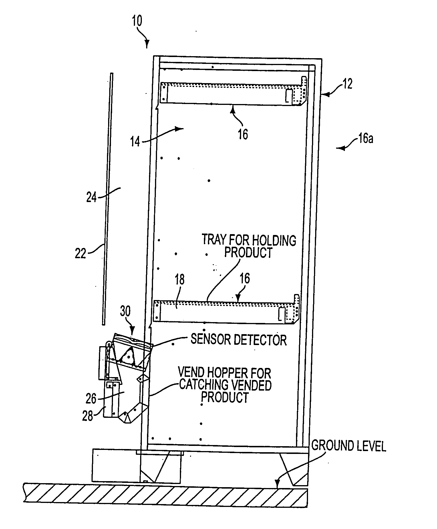
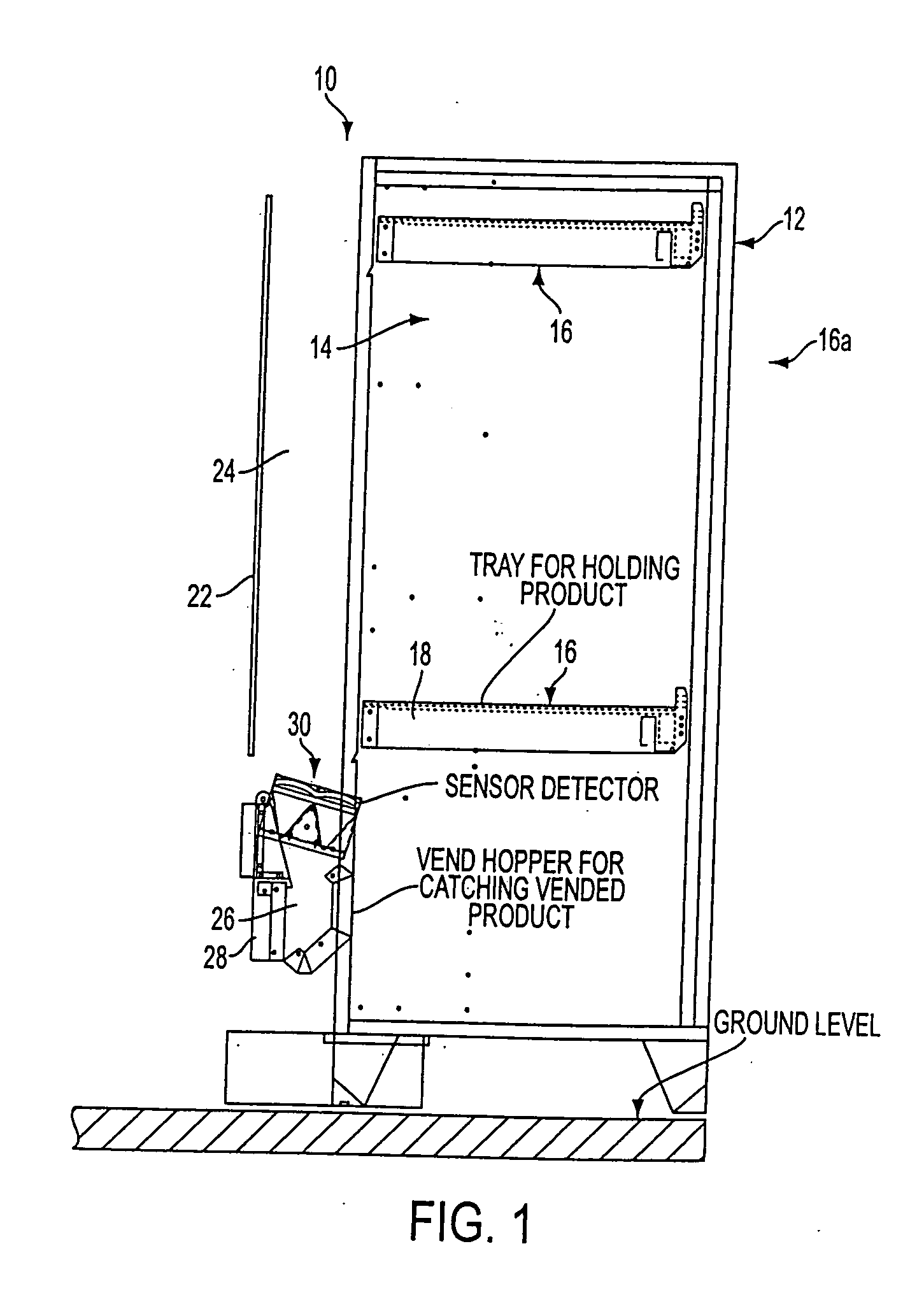
[0045] An exemplary vending machine in which the optical vend-sensing system of the invention may be provided and used, is schematically illustrated at 10 in FIG. 1. Much of the conventional structure has been omitted. In general, the vending machine 10 is shown including a cabinet 12 having opposite sidewalls, a back wall, a top wall and a bottom wall which cooperatively define a forwardly facing cavity 14 arranged to have a plurality of tray assemblies 16 mounted therein at a plurality of vertically spaced levels. In general, the vending machine has an electromechanical dispensing unit 16a. In the example illustrated in FIG. 1, the electromechanical dispensing unit 16a includes the tray assemblies 16. Each tray assembly 16 has a plurality of motorized horizontally arranged spirals which are spaced from one another widthwise of the tray, and each of which extends longitudinally in a front-to-rear depthwise direction of the tray. Each spiral plugs into the driving chuck of a respect...


PUM


Abstract

For ensuring that a vending machine motor will continue to operate until a product has descended through a vending space or an established time interval has elapsed, an optical beam is established across the vend space through which a product must drop. A change in beam intensity is detected. By preference infra red light is emitted at one focal point of an elliptical reflector, and detected at the other focal point. The light is emitted in pulses in the preferred embodiment, and the optical sensing system has automated calibration and error detecting functions.

Description

BACKGROUND OF THE INVENTION [0001] 1. Field of the Invention The present invention pertains to a machine that dispenses objects and detects the dispensed objects with an optical sensor, and more particularly to an optical vend-sensing system and a vending machine that has an optical vend-sensing system. [0002] 2. Description of Related Art [0003] In a typical glass-front vending machine, the user of the machine sees a glass-fronted cabinet, with a selector panel located off to one side of the glass. Through the glass, there can be seen an array of articles, typically packaged snack foods arranged in horizontal columns which extend horizontally in a front-to-rear depthwise direction, with a plurality of columns at each of several vertically spaced levels. At each level the articles are pocketed in-between adjacent turns of respective spirals arranged one or two to a column. Each spiral has an axially central rearwardly projecting stem at its rear, which is plugged into the chuck of a...

Claims


Application Information

Patent Timeline
Patent Type & Authority Applications(United States)
IPC IPC(8): B65G59/00G07F9/02G07F11/04
CPCG07F9/02G07F9/026G07F11/04G07F11/42
Inventor HAIR, JAMES M. IIISPENTZOS, KYRIAKOS P.
Owner AUTOMATED MERCHANDISING SYST
Features
  • R&D
  • Intellectual Property
  • Life Sciences
  • Materials
  • Tech Scout
  • Unparalleled Data Quality
  • Higher Quality Content
  • 60% Fewer Hallucinations
Learn More