Processing Diesel Fuel From Waste Oil

a technology of waste oil and diesel fuel, which is applied in the direction of hydrocarbon distillation, liquid carbonaceous fuels, pyrolysis reactions, etc., can solve the problems of large-scale capital-intensive process facilities, inability to economically re-refine waste oil with known technology, and difficult economics of re-refining waste oil. , to achieve the effect of reducing the cost of waste oil re-refining, low cost, and low cos

Active Publication Date: 2017-05-25
HD PETROLEUM +1
View PDF3 Cites 0 Cited by
  • Summary
  • Abstract
  • Description
  • Claims
  • Application Information

AI Technical Summary

Benefits of technology

[0022]Preferably there is provided a vacuum system for reducing the pressure inside the vertical cylindrical reactor to a value in the range comprising of vertical cylindrical reactor at operating pressure below atmospheric pressure with a preferred range of about 0 kPag to about −35 kPag and a more preferred range of about −7 kPag to about −21 kPag.
[0038]The arrangement described in the embodiments hereinafter is a vertical cylindrical reactor built precisely for this purpose, conducting pyrolysis of waste oil and converting to diesel fuel range hydrocarbons on miniaturized scale that is commercially viable. The invention allows for the continuous pyrolysis of smaller amounts of feedstock to be converted into valuable petroleum distillates. This pyrolysis reduces the cost of waste oil re-refining. The invention achieves this through an optimum residence time under sub atmospheric pressures during the pyrolysis reaction. The reactor achieves this without the use of any catalyst, internally or externally, and has minimal coke formation inside the reactor relative to other prior art. Consequently, the reactor does not require a high frequency of cleaning nor does it require the installation of a bleeding pump or a scrapper like apparatus to continually address the formation of coke inside of the reactor. The device also operates on a continuous basis, thereby causing minimal disruption to overall operations and reducing the need to have multiple reactors or operate the refining process in batches. This also provides a very high yield of diesel fuel range hydrocarbons from the present invention.
[0039]The arrangement described in the embodiments hereinafter provides a novel device operating on a continuous basis where there is a furnace shell, an vertical cylindrical reactor housed inside the furnace shell with a heat deflector placed under the vertical cylindrical reactor and where pyrolysis is caused by heat applied from a burner mounted under the furnace shell under sub-atmospheric pressures with no catalytic additives. The invention includes a vertical cylindrical reactor exposing it to heat from the burner, facilitating a reasonably long residence time for pyrolysis to occur where the resultant vaporised petroleum distillates depart the reactor through a vapour outlet connection located at the top of the vertical cylindrical reactor. Any flue gas generated by the burner can exit the furnace shell through a flue stack located at the top of the furnace shell.
[0040]The arrangement described in the embodiments hereinafter relates to an apparatus for producing petroleum distillates from petroleum based waste oil and such apparatus can be viably incorporated in a re-refining facility. It is suited to any size markets but more particularly in smaller markets which cannot support large-scale refining facilities due to a higher capital, operating and transportation costs. The design of the present device is intended to overcome known limitations in prior art such as non-continuous operation, low product yield, significant coke formation and the use of catalysts inside the reactor by providing suitable designs of a vertical cylindrical reactor which includes a furnace shell with refractory lining, one or more burners situated at the bottom or by the sides, a pressure vessel. The pressure vessel, which is an vertical cylindrical reactor, is designed with a maintenance access way, a feed point, exit point and with related equipment and instrumentation control to obtain optimum conditions that provide an uninterrupted flow of high yield petroleum distillates, primarily in the diesel fuel range, with a minimum coke production without the use of catalysts.
[0048]The present invention relates to a system and method for producing diesel fuel and diesel-like products from petroleum based waste oil in a micro-scale processing facility suitable for operation in any size market, but particularly in smaller markets which cannot support large-scale re-refining facilities. The design of the present system and method is intended to overcome at least some of the limitations in the prior art related to non-continuous operation, lower product yield and substantial coke formation by providing suitable designs of the pyrolysis reactor and related equipment, and operation at suitable process conditions that are most advantageous for high yield of a high quality diesel fuel product with a minimum coke production.

Problems solved by technology

Historically, re-refining waste oil has been difficult to undertake economically unless conducted on a large scale.
While complex large scale processing facilities for recycling waste oils and converting them to reusable products are known, due to the expense of the known technologies, these large-scale capital intensive process facilities are required to draw on large geographical catchment areas for waste oil feedstock.
Due to feedstock, transportation, and logistics costs, which may quickly consume any economies of scale benefit, large scale processing facilities are only viable in large regional markets able to supply sufficient quantities of waste oil feedstock within a reasonable distance.
In smaller and developing markets where such large scale operations are not sustainable, it has not been possible to economically re-refine waste oils with known technology.
Current practices in markets too small to support conventional re-refining facilities include burning waste oil as a dirty fuel for industrial use or space heating, or alternatively disposing of large volumes of waste oil in potentially environmentally inappropriate ways.
These practices may result in a discharge of air borne pollutants, or contamination of soils and groundwater.
Whichever practice is used, the resulting water, soil, and / or air pollution contains many of the harmful chemicals found in waste oil, which may expose plants, animals and humans to their toxic effects.
However, the existing technologies have failed to address the needs for re-refining in small population centres.
They have failed to create a continuous and economically viable process.
These re-refineries have also failed to address low yield and the formation of coke sludge in the processes.
However, this design element ensures that the sludge / coke forming material spends a lot of time near the hottest part of the reactor resulting in increased coke formation.
As a result significant operating and maintenance costs are incurred and loss of production is suffered for the removal and disposal of coke and other heavy by-products.
A number of approaches have been developed to attempt to overcome the coke formation issue and the resultant difficult to control operation.
The heavy fuel oil stream is withdrawn at a rate of approximately 25% of the inlet feed rate and thus significantly reduces the overall process yield to diesel fuel.
An improvement on the process and / or device is claimed in U.S. Pat. No. 7,255,785 issued to Kong and Jeong but it is still a semi-continuous process, results in solidifying sludge cake which must then be removed by means of a bleeding valve at the bottom of the vessel and the process results in only 70 percent conversion of feedstock.

Method used


Image

  • Processing Diesel Fuel From Waste Oil
  • Processing Diesel Fuel From Waste Oil
  • Processing Diesel Fuel From Waste Oil

Examples


implementation example

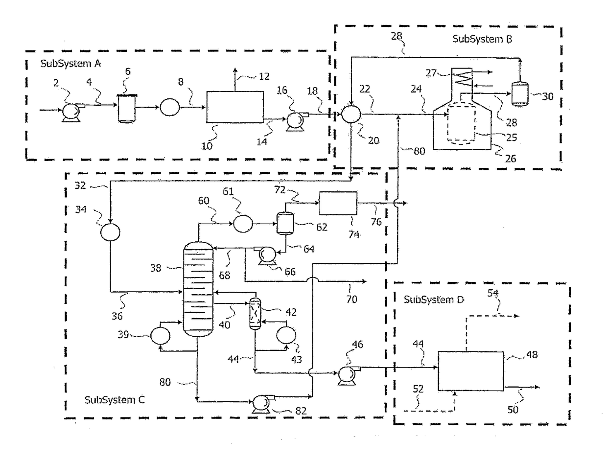
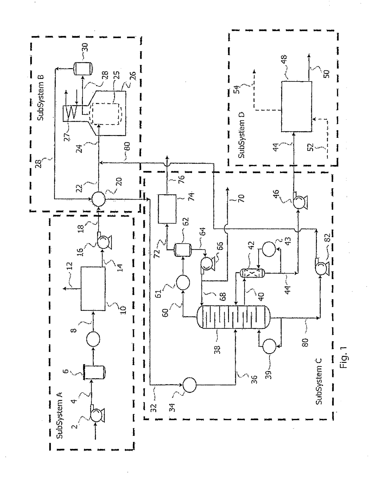
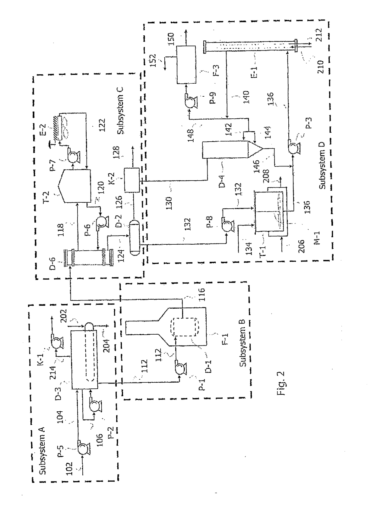
[0096]FIG. 2 and FIG. 3 show a schematic block diagram of an illustrative implementation of the disclosed invention by way of example. This example is an implementation that lends itself best to a prototype or research and development application. This embodiment can be operated in a continuous, semi-batch or batch mode depending on the needs of the user. In a manner analogous to the preferred embodiment previously described, this embodiment also generally comprises four subsystems, including: (i) a dehydration subsystem (Subsystem A); (ii) a thermal reactor subsystem (Subsystem B); (iii) a condensation subsystem (Subsystem C); and (iv) a filtration subsystem (Subsystem D).

[0097]As shown in FIG. 2, Subsystem A is an illustrative dehydration subsystem in which waste oil feed transfer pump (P-5) first continuously brings waste oil from storage (stream 102) that generally contains 5-10% free water and / or emulsified water and transfers it via waste oil dehydrator feed stream 104 to dehy...


PUM

PropertyMeasurementUnit
pressureaaaaaaaaaa
pressureaaaaaaaaaa
pressureaaaaaaaaaa

Abstract

There is disclosed a system and method for processing diesel fuel from petroleum-based waste oil on a small scale compared to conventional methods for re-refining waste oil to a valuable product. In an embodiment, the method comprises dehydrating waste oil to remove water from the waste oil, and operating a vertical cylindrical reactor to induce pyrolysis of the dehydrated waste oil and convert it into a hydrocarbon vapour phase. The hydrocarbon vapour derived from pyrolysis is condensed and distilled using a distillation tower to produce diesel fuel, heavy liquid hydrocarbon, light liquid hydrocarbon and light hydrocarbon vapour. A filtering step cleans the processed diesel fuel to obtain a clean diesel fuel product.

Description

[0001]The present invention relates generally to the field of re-refining or reprocessing petroleum-based waste products, and more particularly to an apparatus and method for processing diesel fuel from waste oil in a micro-scale processing facility.[0002]The present invention also pertains generally to thermal conversion of waste oil in a vertical cylindrical reactor but more particularly it relates to an apparatus or device for pyrolytic or thermal conversion of waste oil where waste oil is heated and decomposed into smaller hydrocarbons inside a pyrolysis device, comprising a reactor, a heater shell and a burner mechanism.BACKGROUND[0003]Historically, re-refining waste oil has been difficult to undertake economically unless conducted on a large scale. While complex large scale processing facilities for recycling waste oils and converting them to reusable products are known, due to the expense of the known technologies, these large-scale capital intensive process facilities are re...

Claims


Application Information

Patent Timeline
Patent Type & Authority Applications(United States)
IPC IPC(8): C10G55/04C10L1/08C10G31/09C10G7/00C10G9/00C10G33/00
CPCC10G55/04C10G9/002C10G33/00C10G31/09C10G7/006C10L2290/547C10L1/08C10L2200/0446C10L2270/026C10L2290/06C10L2290/543C10G7/00C10G25/02C10G31/06C10G53/08B01J19/24B01J6/008B01J2219/00155B01J2219/00157B01J2219/185B01J2219/1943C10G25/00C10G25/003C10G9/24C10G2300/1003C10G2400/04
Inventor MIDDLETON, ORVILLEBERNHARD G.HABICHT, TODDWINRAM, JOHN
Owner HD PETROLEUM
Why Eureka
Try Eureka