Electrical installation for coupling a power supply system and a central direct current branch and method for operating an installation of this type

a technology of electrical installation and power supply system, applied in the direction of emergency power supply arrangement, electrical storage system, greenhouse gas reduction, etc., can solve the problems of economic energy store system low efficiency loss, change in energy distribution conditions, and inability to control, so as to improve network stability, simple and particularly effective

Inactive Publication Date: 2007-04-19
ALSTOM TECH LTD
View PDF12 Cites 11 Cited by
  • Summary
  • Abstract
  • Description
  • Claims
  • Application Information

AI Technical Summary

Benefits of technology

[0004] An object of the invention is to provide an electrical installation for coupling a power supply network and central DC branch, by means of which the stability of the network can be improved in a simple and particularly effective manner, and to provide a method for operating an installation of this type.

Problems solved by technology

These “blackouts” are caused mainly by the malfunctioning of parts of the installation in conjunction with the transmission of power over great distances.
Furthermore, the circumstances of the energy distribution are changing from a combination of energy generation that can be easily controlled and energy consumption that can barely be controlled to a combination of energy generation that cannot be controlled, e.g. wind-energy, and uncontrolled energy consumption.
This new situation requires economic energy store systems with low efficiency losses.

Method used


Image

  • Electrical installation for coupling a power supply system and a central direct current branch and method for operating an installation of this type
  • Electrical installation for coupling a power supply system and a central direct current branch and method for operating an installation of this type
  • Electrical installation for coupling a power supply system and a central direct current branch and method for operating an installation of this type

Examples


Embodiment Construction

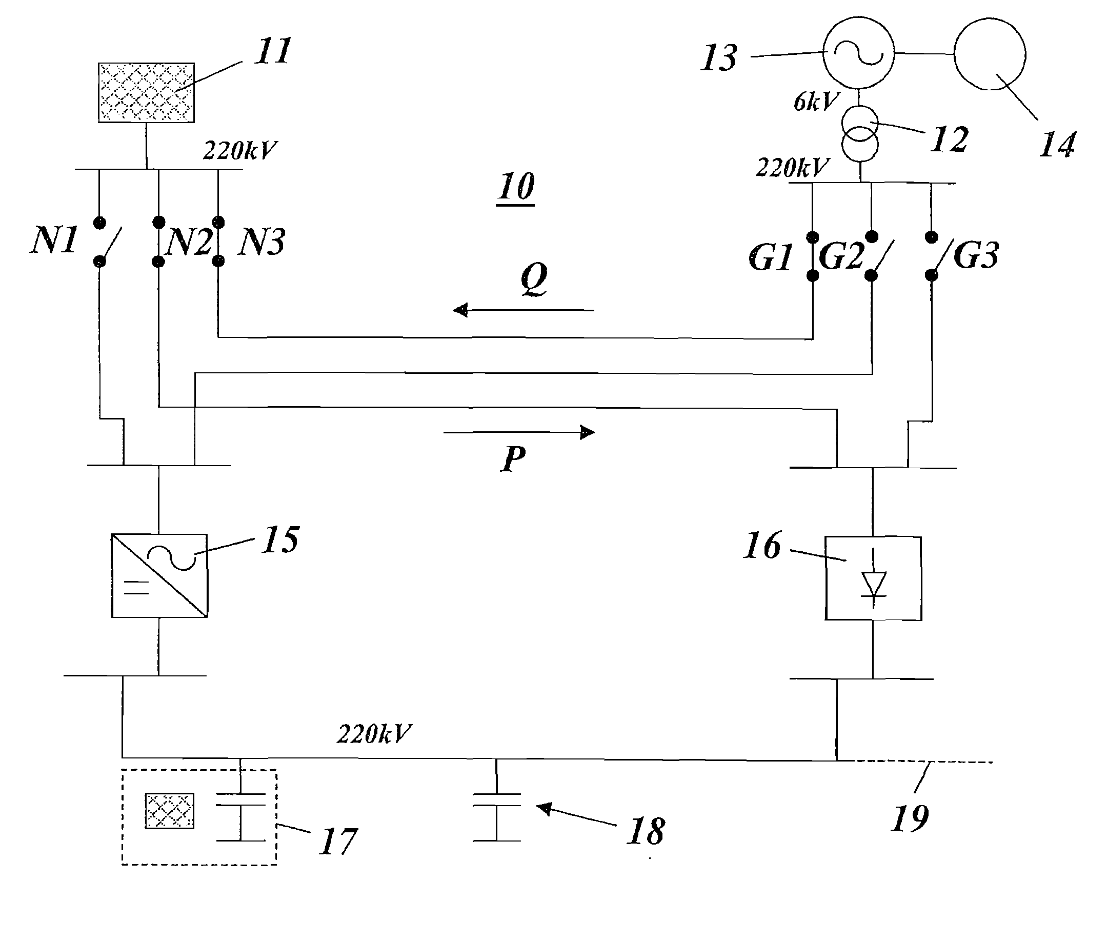
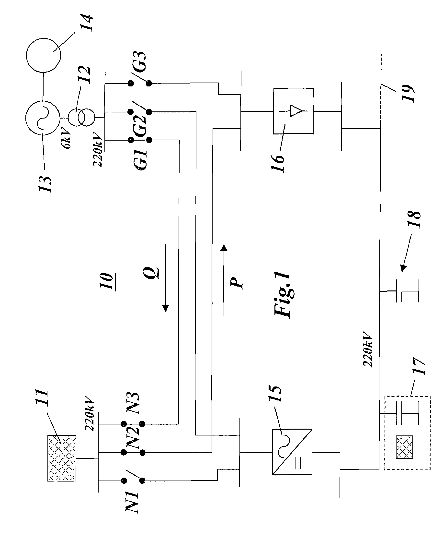
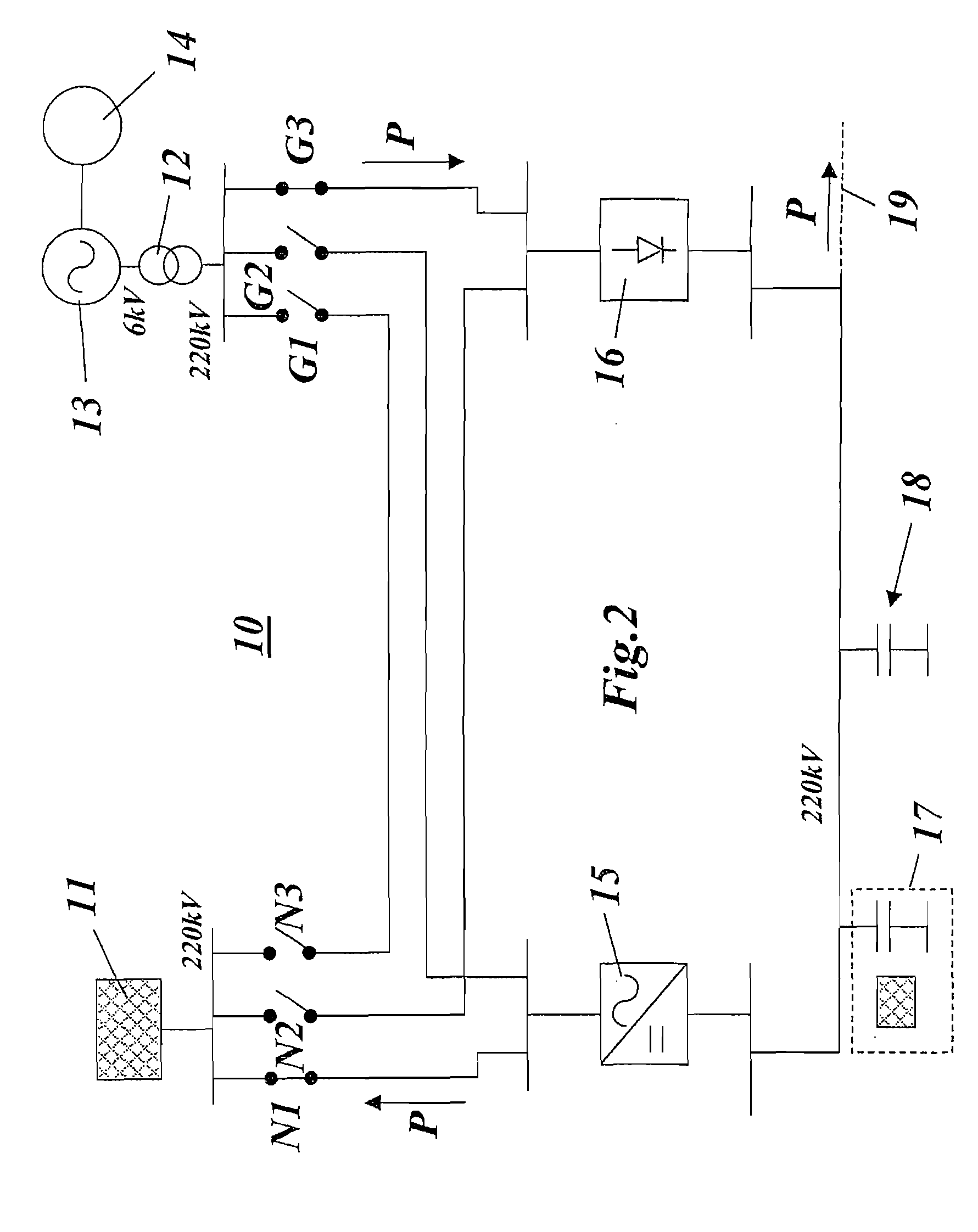
[0025] FIGS. 1 to 5 show the same preferred exemplary embodiment of an electrical installation according to the invention. The process carried out by the installation is different in the individual figures, and in each case results from the different settings of the switches used.

[0026] The electrical installation 10 of FIGS. 1 to 5 includes a coupling between a power supply network 11 (shown symbolically as a cross-hatched block) and one (or more) central DC branch(es) (DC backbone) 19 which are only indicated. Both the power supply network 11 and the central DC branch 19 are in this example at a 220 kV level. Other voltage levels are also conceivable. The central DC branch 19 can establish a connection to other networks. It can also itself be part of a DC network.

[0027] An AC / DC converter 15 is connected by its input to the central DC branch 19 and by its output to a rectifier bridge 16. By means of the network switches N1, N2, the power supply network 11 can selectively draw po...


PUM


Abstract

An electrical installation includes a power supply network, an AC/DC converter, a central DC branch, and a rotating mass energy store. The power supply network is connectable to the central DC branch selectively via one of the AC/DC converter and the rectifier bridge. The rotating mass energy store is connectable to the central DC branch selectively via one of the AC/DC converter and the rectifier bridge and connectable directly to the power supply network. In addition, a method for operating of the electrical installation includes selectively connecting the rotating mass energy store according to a status of the power supply network to the central DC central branch via one of the AC/DC converter and the rectifier bridge and directly to the power supply network

Description

[0001] This application is a continuation of International Application No. PCT / EP / 2005 / 051341, having an international filing date of Mar. 23, 2005, which was published as WO 2005 / 096467 on Oct. 13, 2005, and which claims priority to German Patent Application No. 10 2004 016 034.1, filed on Mar. 30, 2004. The entire disclosure of both applications is incorporated by reference herein.[0002] The invention relates to the field of power supply networks. It concerns an electrical installation for coupling a power supply network and a central DC branch. It also refers to a method for operating an installation of this type. BACKGROUND [0003] In recent years, power supply networks or energy distribution networks have been increasingly affected by what are called “blackouts”. These “blackouts” are caused mainly by the malfunctioning of parts of the installation in conjunction with the transmission of power over great distances. Furthermore, the circumstances of the energy distribution are ch...

Claims


Application Information

Patent Timeline
Patent Type & Authority Applications(United States)
IPC IPC(8): H02J1/10H02J1/16H02J3/28H02J3/30H02J3/32H02J3/38H02J9/04
CPCH02J1/16H02J3/28H02J3/30H02J3/32Y02E60/16Y02E70/30H02J3/386Y02E10/763H02J2300/28H02J3/381Y02E10/76H02J15/007
Inventor DRUBEL, OLIVER
Owner ALSTOM TECH LTD
Why Eureka
Try Eureka