Optical branching unit, and method of manufacturing the same

a branching unit and optical technology, applied in the field can solve problems such as bad uniformity in wavelength of insertion loss of optical branching units, and achieve the effect of low polarization dependent loss and high wavelength uniformity of insertion loss

Inactive Publication Date: 2007-04-19
ORMON CORP
View PDF4 Cites 4 Cited by
  • Summary
  • Abstract
  • Description
  • Claims
  • Application Information

AI Technical Summary

Benefits of technology

[0009] It is an object of the present invention to provide an optical branching unit having a high wavelength uniformity of insertion loss, and a low polarization dependent loss.
[0010] This invention is provided an optical branching unit comprising: a light input part which inputs light; an optical branch which branches the light input to the light input part at a predetermined ratio; a light output part which guides the light branched by the optical branch to a predetermined position; an adhesive layer which is formed to a predetermined thickness on the light input part, optical branch and light output part; a substrate which holds the light input part, optical branch and light output part; a cover member which covers the light input part, optical branch and light output part on the substrate through the adhesive layer; and a stress equalizing member which is provided on the substrate independently of an area provided with the light input part, optical branch and light output part, and prevents a stress generated when the adhesive layer is hardened, from acting on any one or all of the light input part, optical branch and light output part on the substrate.
[0011] According to the above-mentioned optical branching unit, an influence of a stress generated when a cover member is fixed with an adhesive is decreased. Therefore, degradation of polarization dependent loss (PDL) after fixing the cover member is prevented.

Problems solved by technology

However, in the proposal disclosed in the above Publication No. 11-271545, there is a problem peculiar to the structure of an optical branching that is a PLC component.
As a result, the uniformity in a wavelength of insertion loss of an optical branching unit becomes bad.

Method used


Image

  • Optical branching unit, and method of manufacturing the same
  • Optical branching unit, and method of manufacturing the same
  • Optical branching unit, and method of manufacturing the same

Examples


Embodiment Construction

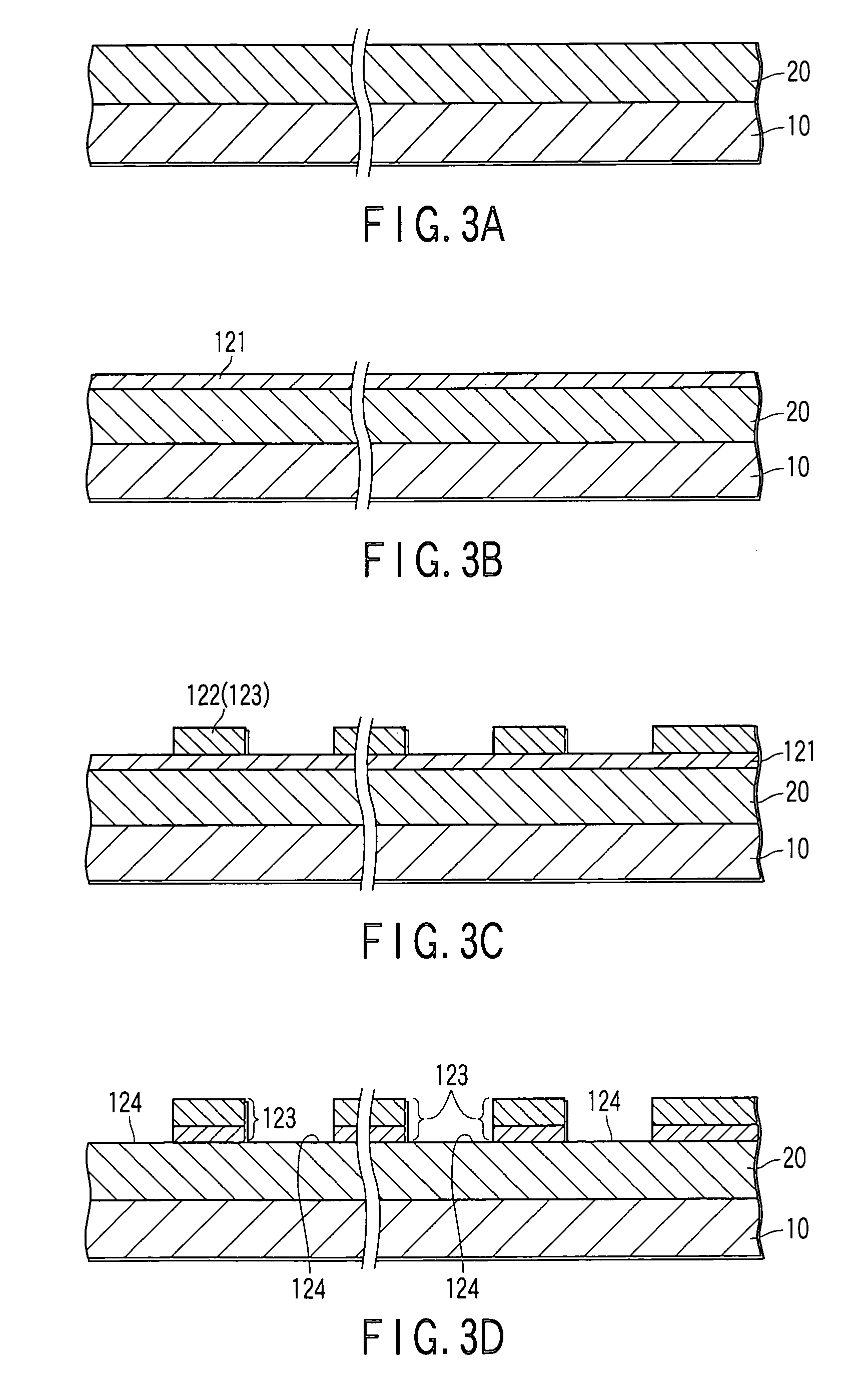
[0031] Hereinafter embodiments of the invention will be explained in detail with reference to the accompanying drawings.

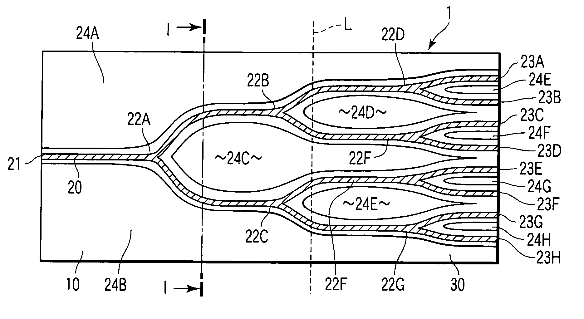
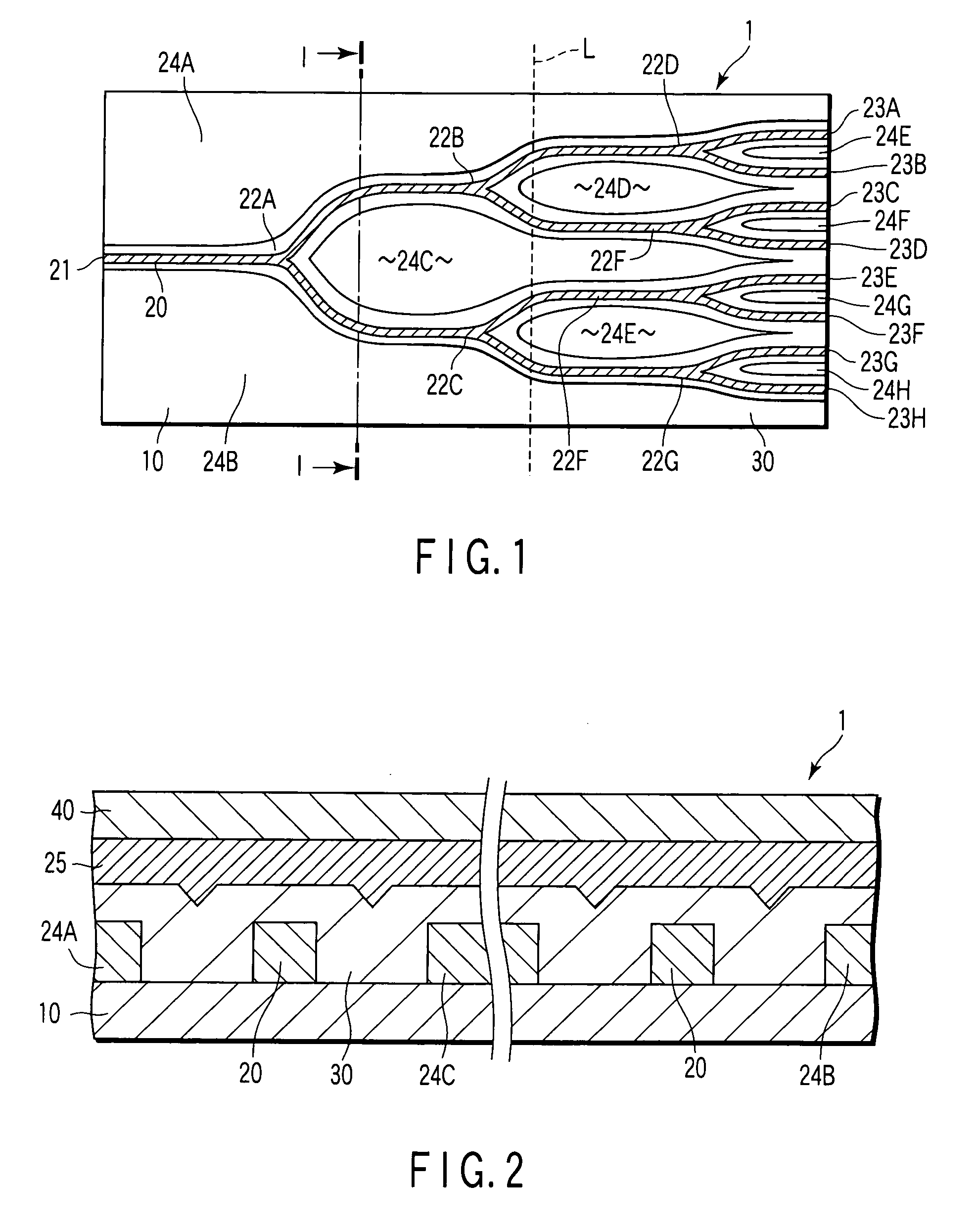
[0032]FIG. 1 is a schematic illustration explaining an example of an optical branching unit according to an embodiment of the invention.

[0033] As shown in FIG. 1, an optical branching unit 1 has a substrate composed mainly of silicon dioxide (SiO2), and an optical waveguide structure 20 formed by patterning in a predetermined shape on the substrate 10. The optical waveguide structure 20 is covered by a member functioning as a clad layer 30 to make the optical waveguide structure 20 usable as a core. A relative index difference between the core portion and clad area (clad layer 30) is 0.45%.

[0034] The optical waveguide structure 20 includes an input end 21 to input a light beam (an optical signal) supplied through a not-show optical transmission member, such as an optical fiber and an optical branching unit in a preceding stage, optical branches 22A-22G to branch...


PUM


Abstract

An optical branching unit according to the invention, has on a substrate, a light input part which inputs light, an optical branch which branches the light input to the light input part at a predetermined ratio, a light output part which guides the light branched by the optical branch to a predetermined position, and a dummy pattern which is provided on a substrate independently of an area provided with the light input part, optical branch and light output part, made of the same material as the light input part, optical branch and light output part, and defined to have an area, so that an occupation rate, or a ratio of the dummy pattern to the area of a substrate except the light input part, optical branch and light output part, is 70% or higher.

Description

CROSS-REFERENCE TO RELATED APPLICATIONS [0001] This is a Continuation Application of PCT Application No. PCT / JP2005 / 009780, filed May 27, 2005, which was published under PCT Article 21 (2) in Japanese. [0002] This application is based upon and claims the benefit of priority from prior Japanese Patent Application No. 2004-157506, filed May 27, 2004, the entire contents of which are incorporated herein by reference.BACKGROUND OF THE INVENTION [0003] 1. Field of the Invention [0004] The present invention relates to an optical branching unit, which is usable in the field of optical communication, and outputs a light beam input to an input end to a plurality of output end. [0005] 2. Description of the Related Art [0006] A PLC (Planer Light Wave Circuit) component is known as an optical waveguide circuit component. As an example of the PLC component, an example has been reported, in which a pattern of an optical waveguide circuit is formed on a silicon substrate, and a partially independe...

Claims


Application Information

Patent Timeline
Patent Type & Authority Applications(United States)
IPC IPC(8): G02B6/255G02B6/122G02B6/125G02B6/13
CPCG02B6/125
Inventor TERADA, YUSUKENATSUME, YUTAKA
Owner ORMON CORP
Why Eureka
Try Eureka