Lens unit and imaging apparatus

a technology of lens unit and lens unit, which is applied in the direction of printers, instruments, cameras, etc., can solve the problem of large arrangement space, and achieve the effect of reducing the arrangement space of the biasing plate spring, efficiently absorbing, and reducing the size of the lens uni

Inactive Publication Date: 2007-04-19
SONY CORP
View PDF7 Cites 49 Cited by
  • Summary
  • Abstract
  • Description
  • Claims
  • Application Information

AI Technical Summary

Benefits of technology

[0011] Accordingly, arrangement space for the biasing plate spring can be reduced, and the downsizing of the lens unit can be realized.
[0012] According to one embodiment of the present invention, since regulating surface sections that regulate movement of the movable part in the optical axis direction are formed in the lens barrel, and regulated surface sections that come into contact with the regulating surface sections of the above-mentioned lens barrel so that the movement is regulated are formed at positions spaced evenly in a circumferential direction of the movable part about an optical axis, impact caused by the contact between the movable part and the lens barrel when the movable part reaches an movement end can be efficiently absorbed, and the posture of the movable part can be stabilized.
[0013] According to one embodiment of the present invention, since first regulated surface sections and second regulated surface sections are formed as the regulated surface sections, and the first regulated surface sections and the second regulated surface sections are different in distance from the regulating surface sections in the optical axis direction, even if large load is applied to the movable part, the large load is not applied only to one of the first regulated surface sections and the second regulated surface sections, so that damage, abras

Problems solved by technology

However, in the above-described conventional imaging apparatus, since there exists a guide mechanism including the guide

Method used


Image

  • Lens unit and imaging apparatus
  • Lens unit and imaging apparatus
  • Lens unit and imaging apparatus

Examples


Embodiment Construction

[0059] Hereinafter, preferred embodiments for carrying out the present invention are described with reference to the accompanying drawings. The present invention can be applied to various types of imaging apparatuses each having a function of moving picture photographing or still picture photographing, such as a cellular phone, video camera, still camera or the like.

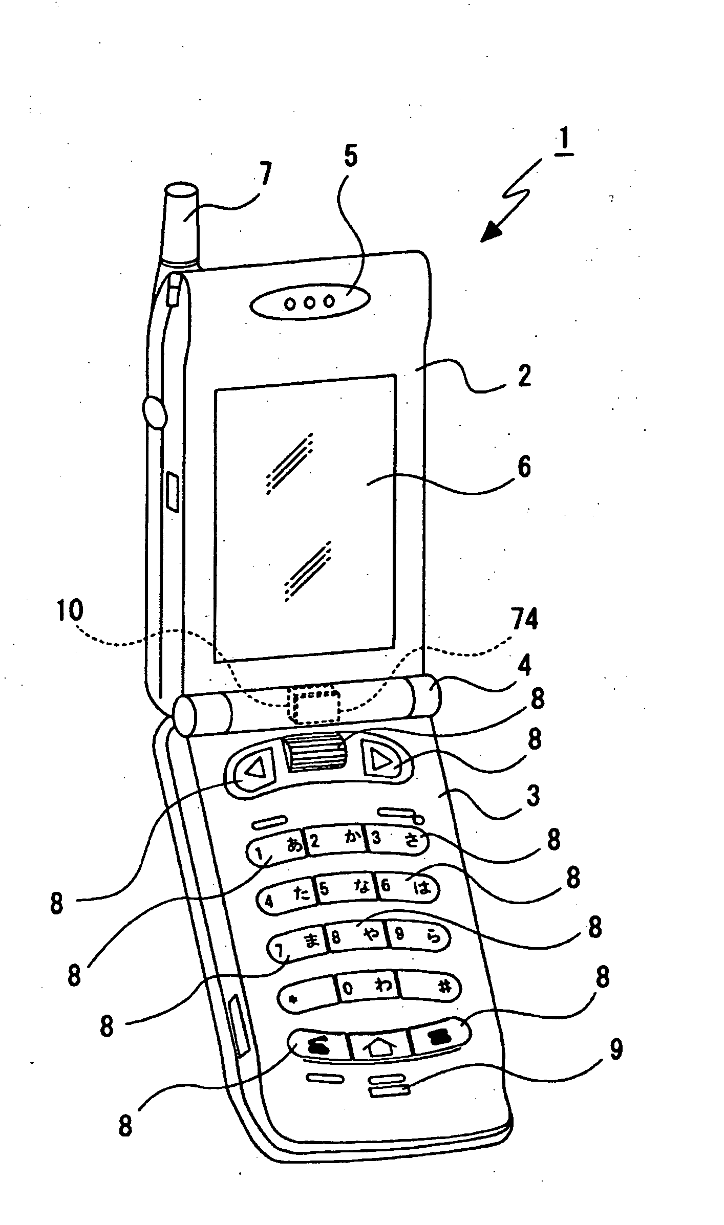
[0060] As an imaging apparatus 1, for example, a cellular phone is shown in FIG. 1. In the imaging apparatus 1, a first casing 2 and a second casing 3 are coupled through a hinge part 4 so as to be freely folded.

[0061] The first casing 2 is provided with a speaker 5, a display part 6 and an antenna 7, and the antenna 7 is constituted flexibly.

[0062] The second casing 3 is provided with various operating parts 8, 8, . . . including push buttons and a rotary dial and a microphone 9.

[0063] An imaging unit 10 and a shutter unit described later are incorporated in the hinge part 4. A predetermined push button of the opera...


PUM


Abstract

A lens unit includes a lens barrel, an imaging system arranged therein; a movable part having a movable lens, moved in an optical axis with respect to the lens barrel; a linear actuator for moving the movable part in the optical axis direction; and a biasing plate spring having a holding section that holds the movable part, spring sections that can be resiliently deformed and bias the movable part in the optical axis direction, and attached sections that are attached to the lens barrel, the thickness direction of the plate spring coinciding with the optical axis, wherein the holding section of the biasing plate spring is formed into a circular arc; and at least a portion of the spring sections of the plate spring are formed into a shape extending in a direction substantially along the holding section on the outer peripheral side of the holding section.

Description

BACKGROUND OF THE INVENTION [0001] 1. Field of the Invention [0002] The present invention relates to a lens unit and an imaging apparatus. More particularly, this invention relates to a lens unit and an imaging apparatus which realize downsizing by holding a movable part by biasing plate springs and devising shapes of the biasing plate springs. [0003] 2. Related Art [0004] A lens unit in which an imaging optical system such as movable lenses is arranged in a lens barrel is incorporated into various types of imaging apparatuses such as a video camera, a still camera and a cellular phone, and there is an imaging apparatus provided with a movable part having movable lenses for zoom or for focus, which can be moved in an optical axis direction by a linear actuator. See Japanese Patent No. 3387173 and Japanese Patent Application Publication No. H8-15593, for example. [0005] In the above-described imaging apparatus, the movable part is supported movably in the optical axis direction by a ...

Claims


Application Information

Patent Timeline
IPC IPC(8): G03B3/10
CPCF16F1/324G02B7/023G02B7/026G02B7/08G02B7/102G02B13/009
Inventor OKITA, ATSUSHIICHIKAWA, MITSURUUNEME, TAKATOSHIKANAI, FUJIO
Owner SONY CORP
Why Eureka
Try Eureka