
Ozone Disinfection Apparatus

a technology of ozone disinfection and apparatus, which is applied in the direction of disinfection, lighting and heating apparatus, combustion types, etc., can solve the problems of high-risk biological warfare agents, ineffectiveness in low concentrations or quantities, and collateral damage to equipment and items within a facility or building, so as to reduce the size of ozonated vapor particles passing through

Inactive Publication Date: 2007-04-19
AGRIMOND USA CORP
View PDF5 Cites 18 Cited by
  • Summary
  • Abstract
  • Description
  • Claims
  • Application Information

AI Technical Summary

Benefits of technology

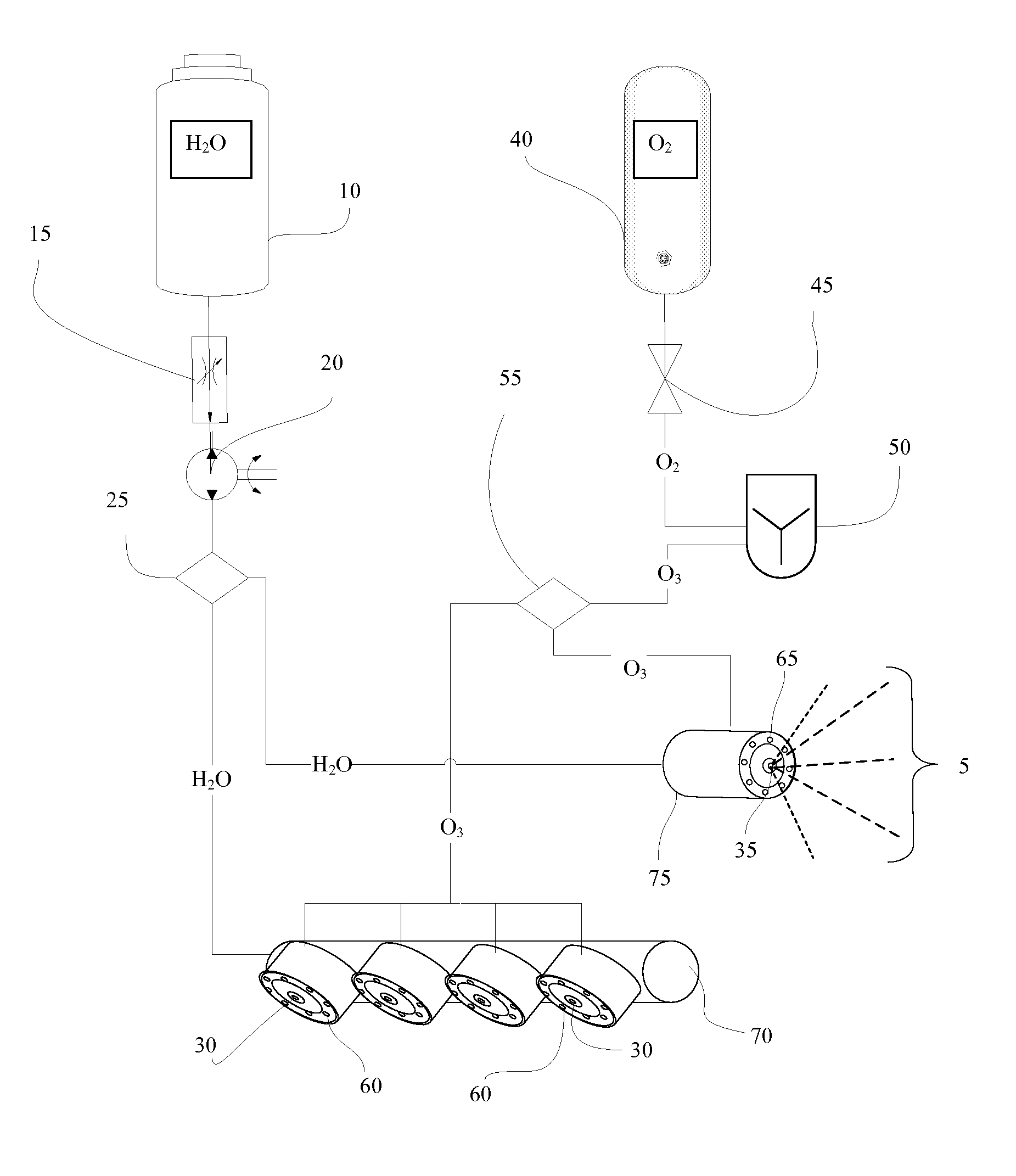
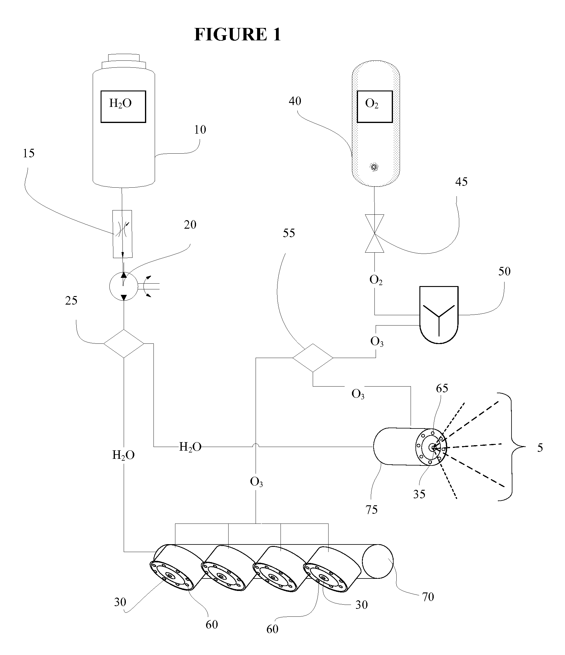
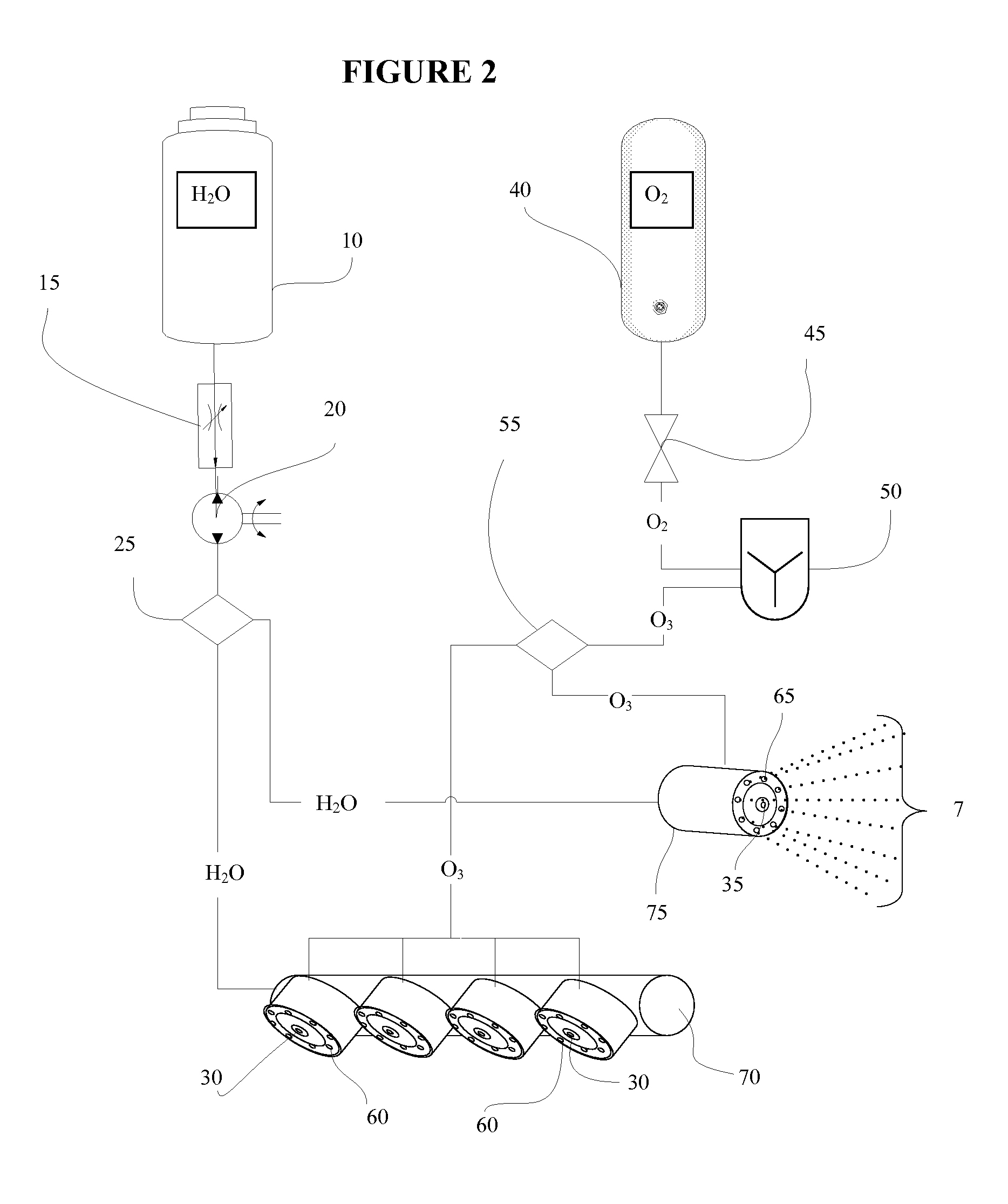
[0009] In an alternate embodiment, the fluid reservoir disposed at the end of the ozone conduit opposite the ozone source such that ozone leaving the ozone conduit is forced into contact with the fluid in the reservoir forming the ozonated vapor. A vapor chamber in fluid communication with the fluid reservoir is adapted to receive the ozonated vapor from the fluid reservoir. In this embodiment, the atomizer is disposed between the vapor chamber and the vapor ejection port and is adapted to reduce the size of the ozonated vapor particles passing through it. In an alternate embodiment, the ozone conduit extends to a point above the level of the fluid in the reservoir and an ozone chamber provides the fluid communication from the ozone conduit to the fluid reservoir but prevents fluid communication between the ozone conduit and the vapor chamber.

Problems solved by technology

Over many years, various highly dangerous biological warfare agents have been developed.
The current technologies have problems such as corrosion, non-effectiveness in low concentrations or quantities, toxic by-products, collateral damage to equipment and items within a facility or building, and logistical issues.
Each of these chemicals requires extensive training and safeguards for hazardous materials handling and storage including costly permits for purchasing in addition to handling and storage.
In higher concentrations required for rapid and complete disinfection they pose a real and dangerous threat if not stored or handled properly.
Additional hazards exist during and even after their use as the area must receive additional cleaning to remove the disinfectant before occupancy.

Method used


Image

  • Ozone Disinfection Apparatus
  • Ozone Disinfection Apparatus
  • Ozone Disinfection Apparatus

Examples


example 1

[0033] In one embodiment, nebulizer 100, as demonstrated in FIG. 6, generates ozonated water vapor, or fog 120. Water reservoir 105 is in fluid contact with ozone conduit 110. The end of ozone conduit 110 is equipped with atomizer 115. During operation ozone passes through conduit 110. A small volume of water from reservoir 105 enters conduit 110 as the ozone passes through. The ozone and water combination is vaporized as it engages atomizer 115. The ozone is absorbed by the vaporized water and eventually becomes dissolved therein; thereby forming the ozonated water vapor 120. Water conduit 107 can be added to the system to replace water lost from the reservoir as vapor 120 is created.

[0034] Vapor 120 then exits the device at ejection port 125 for delivery. Vapor 120 can be dispersed via any known device such as, but not limited to, the hand-held wand, spray bar, or can even be allowed to exit via an open conduit to permeate any room or space. The use of an ozonated fog has applica...

example 2

[0035] Other embodiments of the above described method are envisioned using any know nebulizer. For example, FIG. 7 shows alternate nebulizer 100a. Ozone leaving ozone conduit 110a enters the water contained in water reservoir 105a. Through diffusion and the pressure from conduit 110a, ozonated mist 125a forms within the apparatus where it is either dispersed through ejection port 125a. Alternatively, atomizer 115a can be adapted within the device to reduce the particle size of vapor 120a.


PUM


Abstract

An ozone disinfection apparatus is provided whereby the ozone is dispersed in a vapor. The use of an ozonated vapor increases saturation of the article, surface or area being disinfected. Ozone from a generator on-board the apparatus is forced into contact with a fluid, such as water, to form the vapor. Particle size of the vapor is controlled by passing the vapor through an atomizer.

Description

CROSS REFERENCE TO RELATED APPLICATIONS [0001] This application is a Continuation-in-Part of co-pending U.S. patent application Ser. No. 11 / 160,567, filed Jun. 29, 2005; which claims priority to U.S. Provisional Patent Application 60 / 522,830, filed Nov. 11, 2004; and this application claims priority to currently pending U.S. Provisional Patent Application 60 / 596,861, filed Oct. 26, 2005.FIELD OF INVENTION [0002] This invention relates to the disinfection of articles and surfaces using ozone. BACKGROUND OF THE INVENTION [0003] The new reality of this century is that we are living in a world where airborne hazards of pathogenic microorganisms are a major threat to populations. Whether natural occurrences, industry, terrorism, or warfare causes the threat, it represents an ever-present concern. Attention has been directed to the decontamination of buildings, hospitals, post offices, nursing homes, laboratories, subways, trains, airplanes, structures, equipment, facilities, and even per...

Claims


Application Information

Patent Timeline
IPC IPC(8): A61L2/18
CPCA61L2/202A61L2/22
Inventor TERAN, ALFREDO J.SAMAD, NIDAL A.MANGIACAPRA, LOUIS V.
Owner AGRIMOND USA CORP
Learn More