Insulating glass unit

a technology of insulating glass and units, which is applied in the direction of doors/windows, building components, construction, etc., can solve the problems of blindness of the insulating glass unit, irreparable damage, and no longer insulate as desired, and achieve the effect of simple and cost-effective manufacturing

Inactive Publication Date: 2007-04-19
USD FORMTEILTECHN
View PDF3 Cites 31 Cited by
  • Summary
  • Abstract
  • Description
  • Claims
  • Application Information

AI Technical Summary

Benefits of technology

[0014] The object of the present invention is therefore to provide an insulating glass unit which is simple and cost-effective to manufacture, and which has a sufficiently tightly sealed pane intermediate space even in the event of frequent and rapid air pressure changes. Furthermore, the insulating glass unit according to the present invention is to be producible using a minimum of adhesive.

Problems solved by technology

If it leaks, inter alia, the thermally insulating gas filling may escape, for example, or moisture may collect in the insulating glass unit and condense on the interiors of the panes.
The insulating glass unit then becomes “blind,” no longer insulates as desired, and is typically irreparably damaged.
However, because of its low material strength, the gap seal cannot contribute to the mechanical strength of the edge connection.
It has been shown that the currently typical insulating glasses generally do not meet this standard, in particular, in the event of air pressure changes rapidly following one another.
In general, pressure changes result in deformations of the insulating glass units.
The related art also has the disadvantage that the use of adhesive for fixing the panes slows the manufacturing of the insulating glass unit and additionally stresses the environment.
The components of the insulating glass units of the related art which are glued to one another are additionally unsuitable for recycling.

Method used


Image

  • Insulating glass unit
  • Insulating glass unit
  • Insulating glass unit

Examples


third embodiment

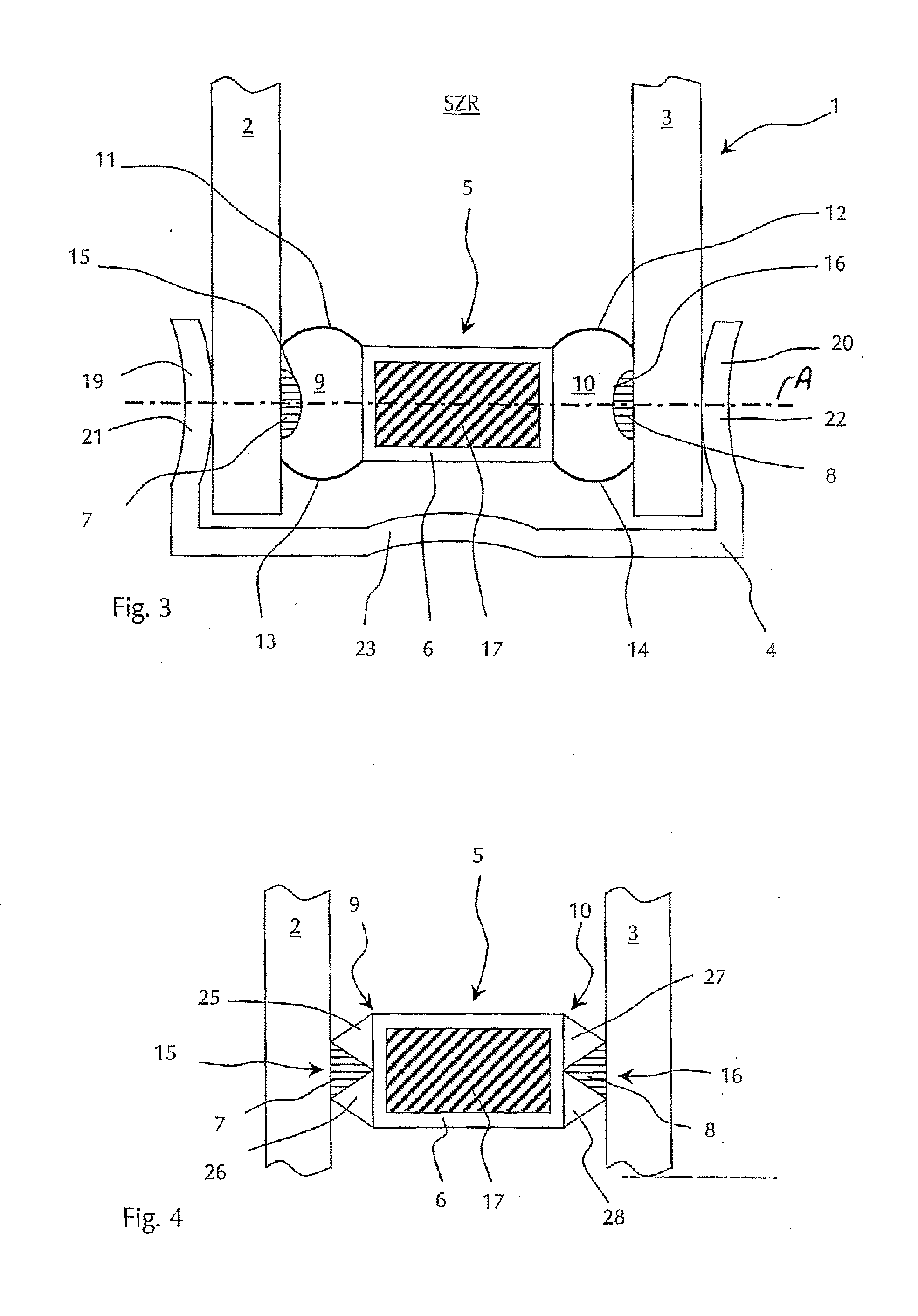
[0053]FIG. 4 shows a detail of an especially preferred third embodiment of an insulating glass unit according to the present invention, in which the cushions 9, 10 of the sealing element 5 each comprise two prismatic elastomeric profiled strips 25, 26 and 27, 28. The clamp 4 located on the edge is not shown in this illustration, although this embodiment is also a clamped insulating glass unit 1 The cushioning strips 25, 26 and 27, 28 are each situated in pairs next to one another in such a way that a trough 15 or 16 having a triangular cross-section results between them in each case. A gap seal 7, 8 made of polyisobutylene is situated in each trough 15, 16. The cushion surfaces facing toward the pane intermediate space SZR are not provided with a metal coating in this embodiment.

fourth embodiment

[0054] In the insulating glass unit 1 of FIGS. 5 & 6, the sealing element 5 again has two permanently elastic cushions 9, 10 which are not provided with a metal coating. Experiments have shown that metallic surfaces of the cushions 9, 10 may be dispensed with in many applications, since the cushions 9, 10 are usually sufficiently tight to vapor diffusion. To adsorb water vapor from the pane intermediate space SZR, the sealing element 5 has a hollow profile 6 which is open to the desiccant containing cavity 17 through perforations 24.

[0055] In this embodiment as well, the glass panes 2, 3 and the sealing element 5 are fixed entirely without the aid of an adhesive, in this case using multiple clamps 4 and a tensioned tension band 29. The tension band 29 is guided in recesses 23 of the clamps 4, and thus, secured against lateral slipping on the clamp backs 18. As may be seen in the side view of the insulating glass unit 1 in FIG. 6, the tension band 29 runs parallel to and around the p...


PUM


Abstract

An insulating glass unit having at least two glass panes, a fastener for fixing the position of the glass panes and a sealing element for setting a distance between two neighboring panes and for gas-tight, lateral insulation of the pane intermediate space enclosed by the panes, the sealing element containing at least one gas-tight middle part and two lateral gap seals, each of which is situated in the area between one of the glass panes and the middle part, at least one diffusion-tight cushion, which is essentially made of an elastic material, being situated in the area between the two gap seals of the sealing element. The inner surfaces of the cushion preferably have a metal layer vapor-deposited on them. In a preferred embodiment, the fastener is a metal clamp externally enclosing the panes which enables the insulating glass unit to be manufactured essentially without adhesive.

Description

BACKGROUND OF THE INVENTION [0001] 1. Field of the Invention [0002] The present invention relates to an insulating glass unit having at least two glass panes, a fastener for fixing the position of the glass panes, and a sealing element for setting a distance between two neighboring panes and for gas-tight lateral insulation of the pane intermediate space enclosed by the panes. In particular, the present invention relates to such an insulating glass unit, in which the sealing element contains at least one gas-tight middle part and two lateral gap seals, each of which is situated between a glass pane and the middle part. [0003] 2. Description of Related Art [0004] As also described in German industrial standard (DIN) 1259, part 2, in such a glazing unit, also referred to as multi-pane insulating glass, glass panes made of window glass mirror glass, cast glass, flat glass, or similar glasses are typically used. The glass panes are separated from one another by one or more intermediate ...

Claims


Application Information

Patent Timeline
Patent Type & Authority Applications(United States)
IPC IPC(8): E06B3/00E06B3/663
CPCE06B3/66342
Inventor DIERKS, KATI-JOSEF
Owner USD FORMTEILTECHN
Why Eureka
Try Eureka