Fuel cell system and shutoff method

a fuel cell and system technology, applied in the direction of fuel cells, electrochemical generators, electrical equipment, etc., can solve the problems of fuel cell output electricity decline, fuel cell water remaining on the walls of gas passages and in the electrolytic membrane of the fuel cell, and fuel cell, which is possibly used in cold-temperature regions, to achieve efficient discharge of condensed water

Inactive Publication Date: 2007-04-19
HONDA MOTOR CO LTD
View PDF1 Cites 18 Cited by
  • Summary
  • Abstract
  • Description
  • Claims
  • Application Information

AI Technical Summary

Benefits of technology

[0019] The actual temperature of the fuel cell is not higher than the predetermined temperature when the instruction for shutoff of electricity generation is transmitted after the fuel cell is started in the low-temperature operation mode. Accordingly, the water vapor (water), which is produced as a by-product during the electricity generation carried out before the shutoff, tends to condense in the reactive gas passage. Due to the resulting condensed water, it is difficult for water in the MEA to migrate into the reactive gas passage. The fuel cell system described above, in which the humidifier controller controls the humidifier so as not to humidify the scavenging gas, is able to supply the dry scavenging gas without humidification. Because the condensed water tends to evaporate to be absorbed into the dry scavenging gas, it is possible to efficiently discharge the condensed water and then to shutoff the fuel cell system. As a result, the fuel cell can provide proper generation of electricity at a subsequent startup.

Problems solved by technology

It is feared that a fuel cell, which is possibly used in cold-temperature regions, encounters freezing if there remains water in the fuel cell.
This freezing leads to blockades for gas passages in the fuel cell, which possibly cause a decrease in output electricity of the fuel cell during a subsequent startup.
However, although scavenging is conducted during a shutoff of the fuel cell, it sometimes occurs that water remaining on walls of the gas passages and in electrolytic membranes of the fuel cell happens to freeze eventually.
In this case, electrolytic membranes and the like are possibly dehydrated too much, which results in a possible decrease in output electricity of the fuel cell during its subsequent startup.
Because water vapor (water), which is produced before turning off IG as a by-product in parallel with electricity generation, happens to condense in the fuel cell, the resulting condensed water possibly causes a decrease in output electricity of the fuel cell during its subsequent startup.

Method used


Image

  • Fuel cell system and shutoff method
  • Fuel cell system and shutoff method
  • Fuel cell system and shutoff method

Examples


Embodiment Construction

[0029] An embodiment of the present invention is now described with reference to FIGS. 1 to 6.

1. Architecture of Fuel Cell System

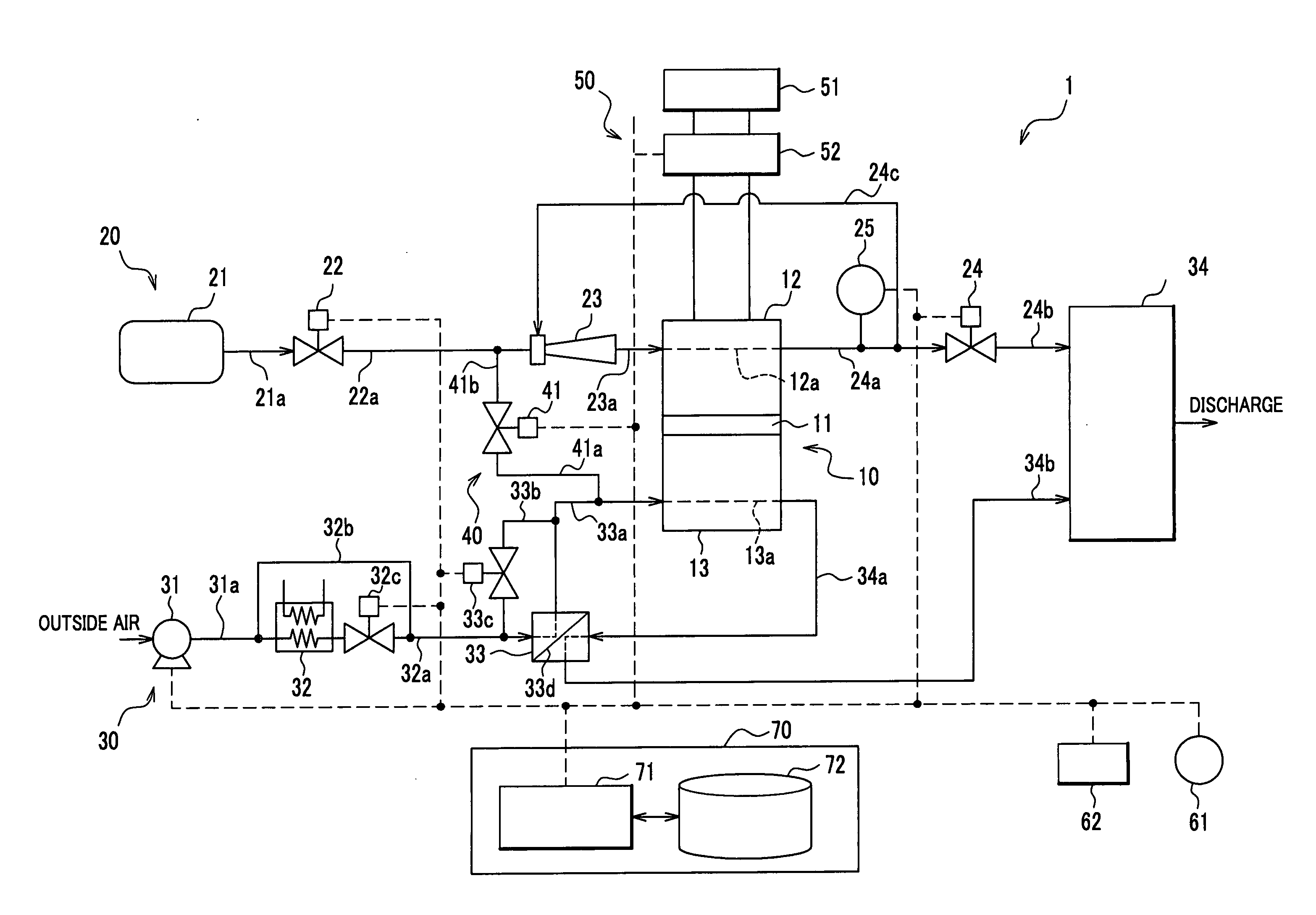
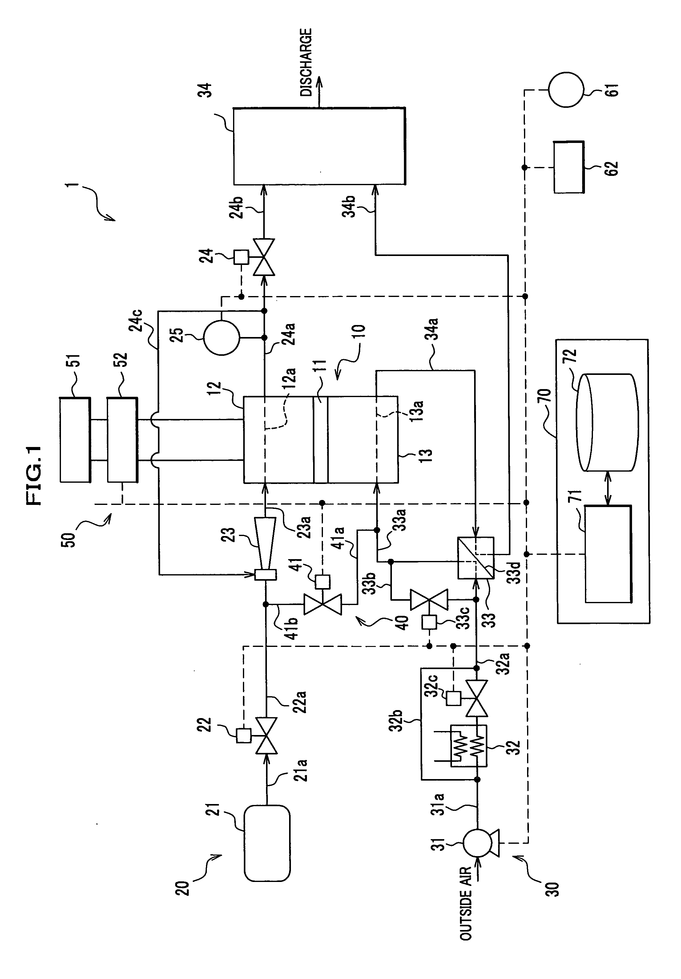
[0030] As shown in FIG. 1, a fuel cell system 1 is mounted on a fuel cell automobile. The fuel cell system 1 has a traction motor 51, which is electrically connected with output terminals (not shown) of a fuel cell 10. The fuel cell automobile is driven by the traction motor 51, which is energized by electricity generated by the fuel cell 10.

[0031] The fuel cell system 1 includes a fuel cell 10, an anode system 20, a cathode system 30, a scavenging system 40, a power consumption system 50, an ambient temperature sensor 61, an electronic control unit (ECU) 70 and the like. The anode system 20 supplies hydrogen (fuel gas, reactive gas) to the fuel cell 10 and discharges it from the fuel cell 10. The cathode system 30 supplies air containing oxygen (oxidant gas, reactive gas) to the fuel cell 10 and discharges it from the fuel cell 10. The scavenging syst...


PUM

PropertyMeasurementUnit
currentaaaaaaaaaa
temperatureaaaaaaaaaa
electric potentialaaaaaaaaaa

Abstract

A fuel cell system includes a fuel cell, an operation controller, a checking unit, a scavenging unit, an instructing unit, a temperature sensor, a humidifier and a humidification controller. The operation controller selects one of a normal operation mode and a low-temperature operation mode. The checking unit determines whether the fuel cell has been started up in the low-temperature operation mode. The instructing unit provides an instruction for a shutoff of electricity generation. When the scavenging unit conducts scavenging based on the checking unit determining that the fuel cell has been started in the low-temperature operation mode in response to an instruction for a shutoff of electricity generation and an actual temperature of the fuel cell is higher than a predetermined temperature, the humidification controller controls an amount of humidification according to the actual temperature.

Description

BACKGROUND OF THE INVENTION [0001] The present invention relates to a fuel cell system and a shutoff method for the system. [0002] Development of fuel cell automobiles has prevailed in recent years, on which fuel cells such as Polymer Electrolyte Fuel Cells (PEFC) are mounted. A fuel cell automobile of this type is driven by a motor, to which electricity generated by a fuel cell is supplied. [0003] Generally speaking, a fuel cell has a stack structure, which is made of a plurality of stacked unit cells. A unit cell has a membrane electrode assembly (MEA). When hydrogen and air containing oxygen are supplied to an anode and a cathode in the MEA, respectively, electric potential difference occurs in the unit cell. The fuel cell, which is electrically connected to an external load such as a motor, generates electricity. [0004] The fuel cell described above produces water at the cathode while it is generating electricity. In order to maintain a moist condition for an electrolytic membra...

Claims


Application Information

Patent Timeline
Patent Type & Authority Applications(United States)
IPC IPC(8): H01M8/04
CPCH01M8/04007H01M8/04231H01M8/0432H01M8/04343H01M8/04753H01M8/04761H01M8/04835Y02E60/50
Inventor INAI, SHIGERUWAKE, CHIHIROMIYATA, KOICHIROJINBA, RYO
Owner HONDA MOTOR CO LTD
Why Eureka
Try Eureka