Process for machining in situ the peripheral surface of a rotating part, and apparatus for carrying out said process

a technology for rotating parts and peripheral surfaces, which is applied in the direction of metal-working holders, positioning devices, support devices, etc., can solve the problems of immobilisation of the motor for a long period, high cost of repair, and the inability to rotate contacts in a uniform radius around their entire periphery, etc., and achieve the effect of smooth plate movemen

Inactive Publication Date: 2007-04-19
CARBONE LORRAINE APPL ELECTRIQUES
View PDF12 Cites 1 Cited by
  • Summary
  • Abstract
  • Description
  • Claims
  • Application Information

AI Technical Summary

Benefits of technology

[0038] Preferably, the plate is not fixed directly on a fixed point of the frame, but onto a base fixed onto the said frame. The base itself is provided with a second slide running along the XX′ direction substantially parallel to the axis of rotation xx′ of the rotating part, and the plate is provided with a second traveller, ...

Problems solved by technology

It is observed that these rotating contacts do no longer have a uniform radius around their entire periphery after the motor has been in operation for some time.
This type of repair is usually an expensive operation that immobilises the motor for a long period.
This has several disadvantages; firstly, a stock of spare motors has to be provided that will be used for the repair time of the disassembled motors; and secondl...

Method used


Image

  • Process for machining in situ the peripheral surface of a rotating part, and apparatus for carrying out said process
  • Process for machining in situ the peripheral surface of a rotating part, and apparatus for carrying out said process
  • Process for machining in situ the peripheral surface of a rotating part, and apparatus for carrying out said process

Examples


Embodiment Construction

[0041] Figures

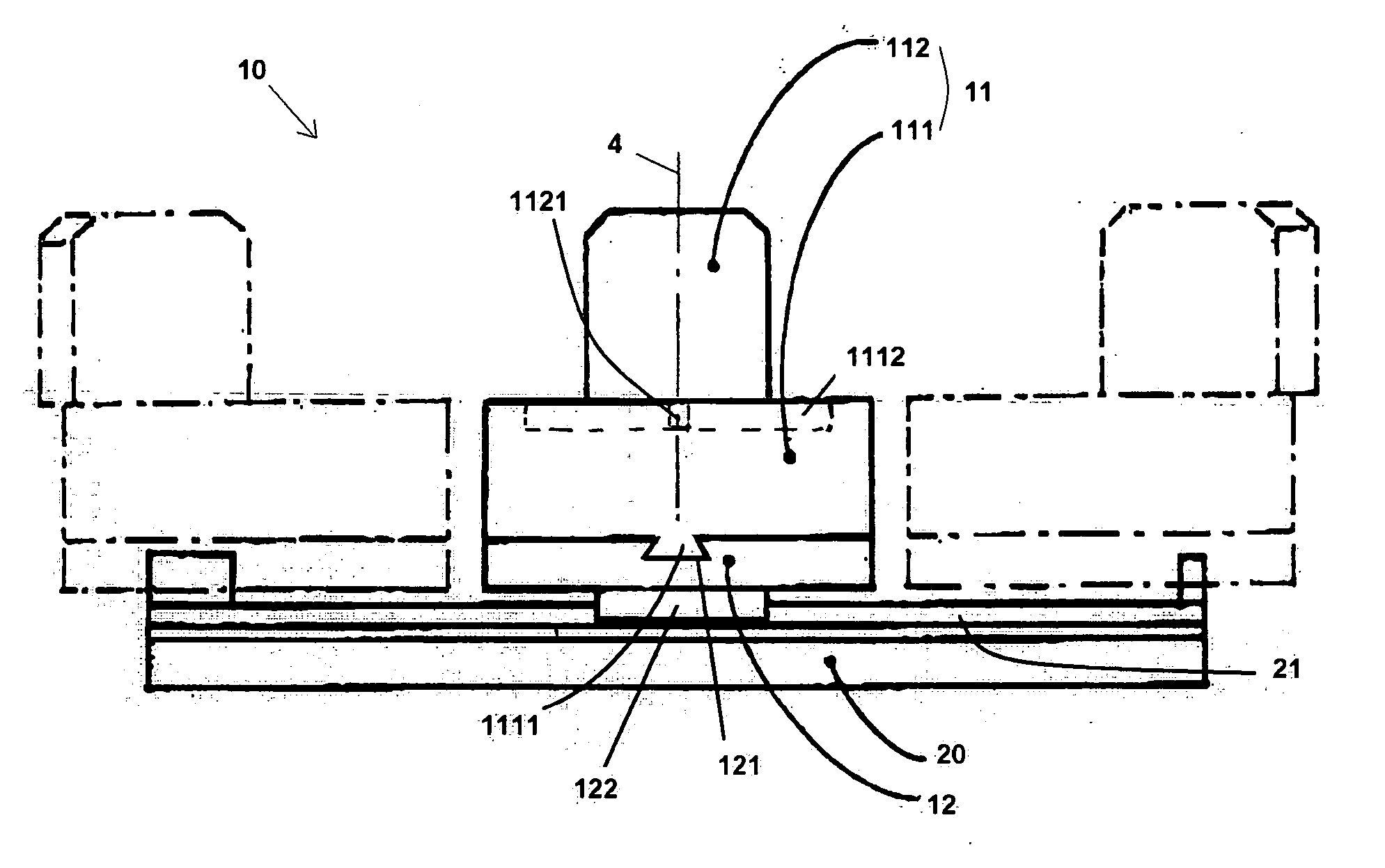
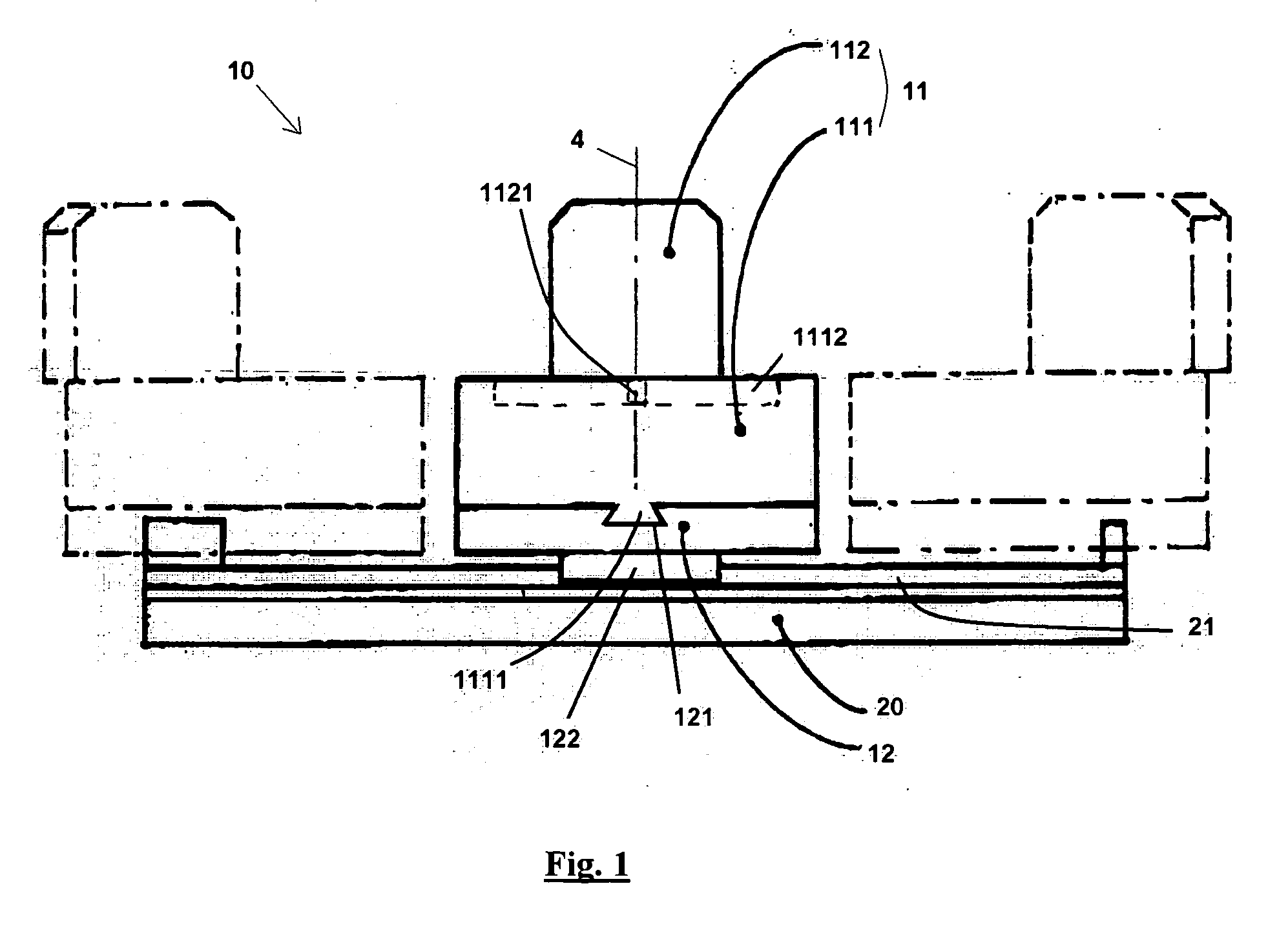
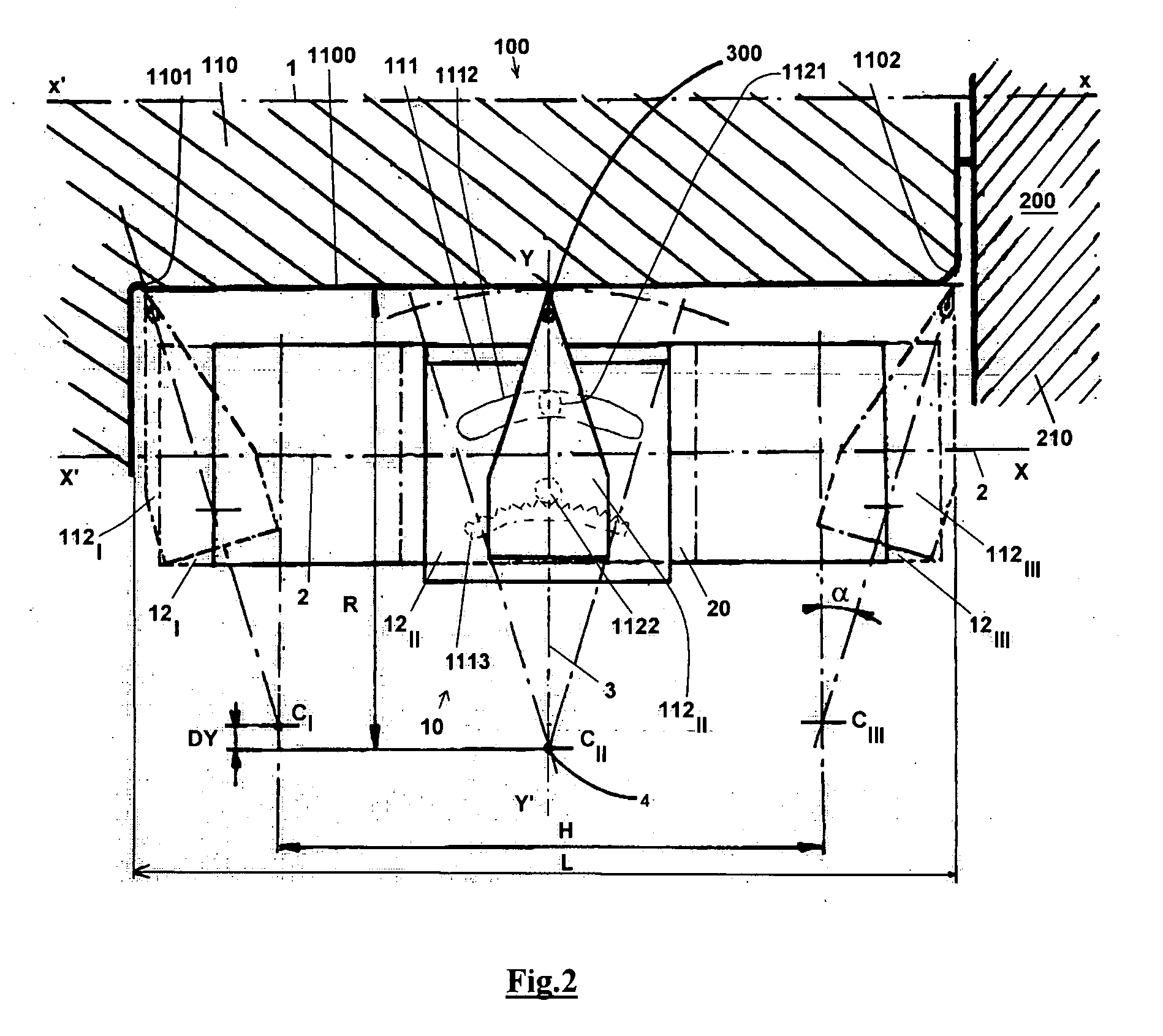
[0042]FIG. 1 illustrates a front view and FIG. 2 illustrates a top view of a machining device according to the invention used for in situ resurfacing of the surface of rotating contacts of electrical motors, with the extreme spatial configurations of the plate and tool holder shown in chain dotted lines.

[0043] The machining device shown in this example includes two parts: a base (20) fixed to the frame of the motor (not shown) and a plate+tool holder assembly (10). The tool holder (11) is fitted at its end with a hard machining tip (300), typically greater than 10 on the Mohs scale, for example made of diamond. The tool holder comprises two parts free to move with respect to each other: [0044] a base (111) that can displace along YY′ and is provided with a gear (1113) moving around the arc of a circle in a plane parallel to (XX′, YY′) and a groove (1112) in the form of an arc of a circle concentric to the arc of circle in the gear; [0045] an insert holder (112) that h...


PUM

PropertyMeasurementUnit
Fractionaaaaaaaaaa
Angleaaaaaaaaaa
Diameteraaaaaaaaaa

Abstract

Process for machining in situ the peripheral surface (1100) of a rotating part, rotating around an xx′ axis (1), wherein a machining device is used comprising at least one plate (12) fixed to a frame and a tool holder (11) provided with a cutting tool (300), and mounted on the said plate such that it can move along a YY′ direction (3) substantially perpendicular to the xx′ axis of rotation (1). The tool holder is installed on the plate (12) such that it can pivot around an axis oriented along a ZZ′ direction (4) substantially perpendicular to the YY′ direction and to the xx′ axis of rotation. By combining a rotation of the tool holder around the XX′ axis and a translation of the centre (C) of rotation around the ZZ′ axis along the in-feed direction YY′, a displacement is imposed on the active end of the cutting tool (300) in a plane perpendicular to the ZZ′ axis. The device may also move along the third XX′ axis.

Description

DOMAIN OF THE INVENTION [0001] The invention relates to machining of rotating parts on site (on a machine and in the factory), and particularly to the renovation of commutators fixed to the armature or the rotor respectively of electrical motors, and that we will subsequently call “rotating contacts”. BACKGROUND OF THE INVENTION [0002] The invention was developed more particularly in order to renovate the surfaces of commutators or slip-rings that have peripheral circularity defects resulting from the friction of the brushes that maintain a sliding electrical contact with them. It is observed that these rotating contacts do no longer have a uniform radius around their entire periphery after the motor has been in operation for some time. To prolong the life of rotating contacts, limit brush wear and eliminate mechanical vibrations, a repair is made by abrasion resurfacing, typically “by stone” or grinding wheel, or by machining of the degraded surface. [0003] This type of repair is u...

Claims


Application Information

Patent Timeline
IPC IPC(8): B23Q3/155
CPCB23B1/00Y10T82/10Y10T82/16016H01R43/06
Inventor OVAERE, PETERBECQUET, YVON
Owner CARBONE LORRAINE APPL ELECTRIQUES
Why Eureka
Try Eureka