
Linear device

a linear device and electrode technology, applied in the field of linear devices, can solve the problems of reducing the strength of the glucose sensor, affecting the treatment effect, so as to prevent damage, reduce the damage to the subject and the linear device, and prevent damag

Inactive Publication Date: 2007-04-19
YASUZAWA MIKITO +1
View PDF4 Cites 43 Cited by
  • Summary
  • Abstract
  • Description
  • Claims
  • Application Information

AI Technical Summary

Benefits of technology

[0010] Accordingly, the object of the present invention is to provide a linear device which is slim, can be inserted into a desired region of a subject, and minimizes the damage to the subject.

Problems solved by technology

However, the diameter of the glucose sensor of Prior Art 1 is about 0.8 mm and that of the glucose sensor of Prior Art 2 is at least 0.35 mm; accordingly, when the glucose sensors are stuck into the human body, many cells are damaged.
If the glucose sensors are embedded and left in a region of the human body, the region aches or feels uncomfortable.
However, the strength of the glucose sensor too is reduced; accordingly, it may be difficult to insert the glucose sensor into the human body or the glucose sensor may buckle while it is being inserted into the human body.
Thus, it may be difficult to apply the glucose sensor to a desired region of the human body.
If the glucose sensor is bent and broken in a region of the human body, the sensor stops functioning and the region may be damaged and ache.
Besides, because the glucose sensor of Prior Art 1 has a large diameter and its titanium-oxide electrode too is large, it cannot be used for the measurement of the density of glucose in minute regions such as local regions in the brain.

Method used


Image

  • Linear device
  • Linear device
  • Linear device

Examples


Embodiment Construction

[0045] A preferred embodiment of the present invention will be described below by referring to the drawings.

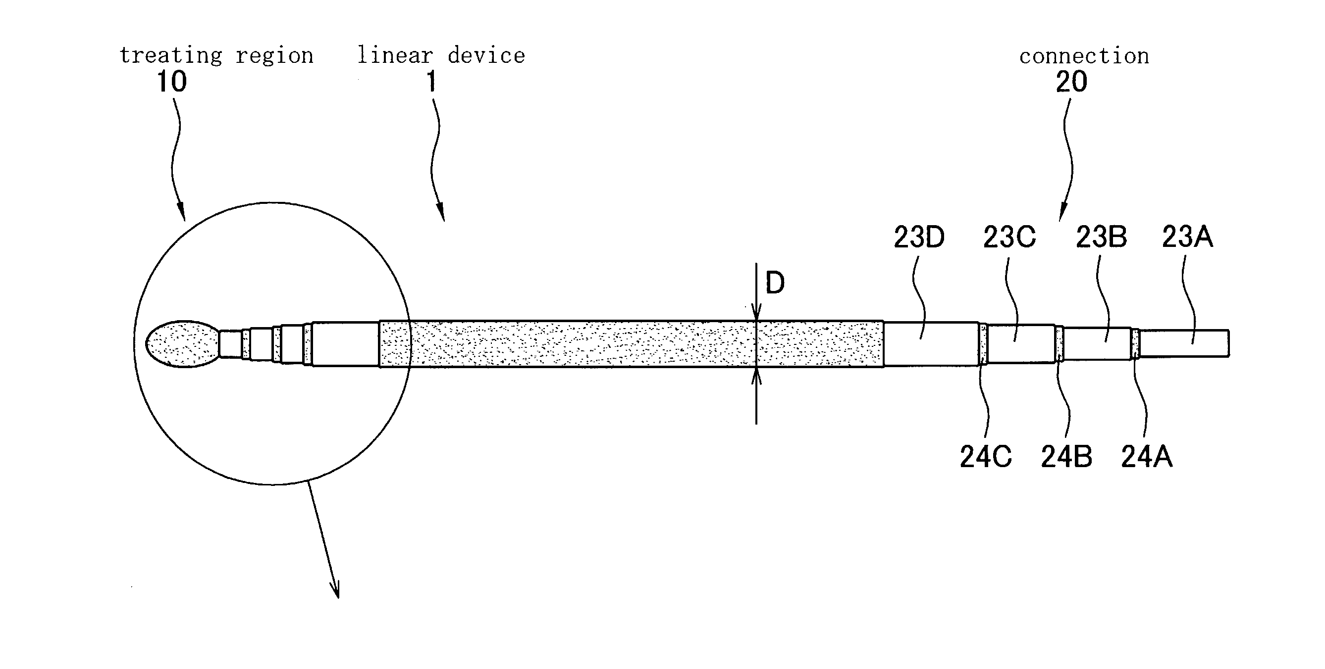
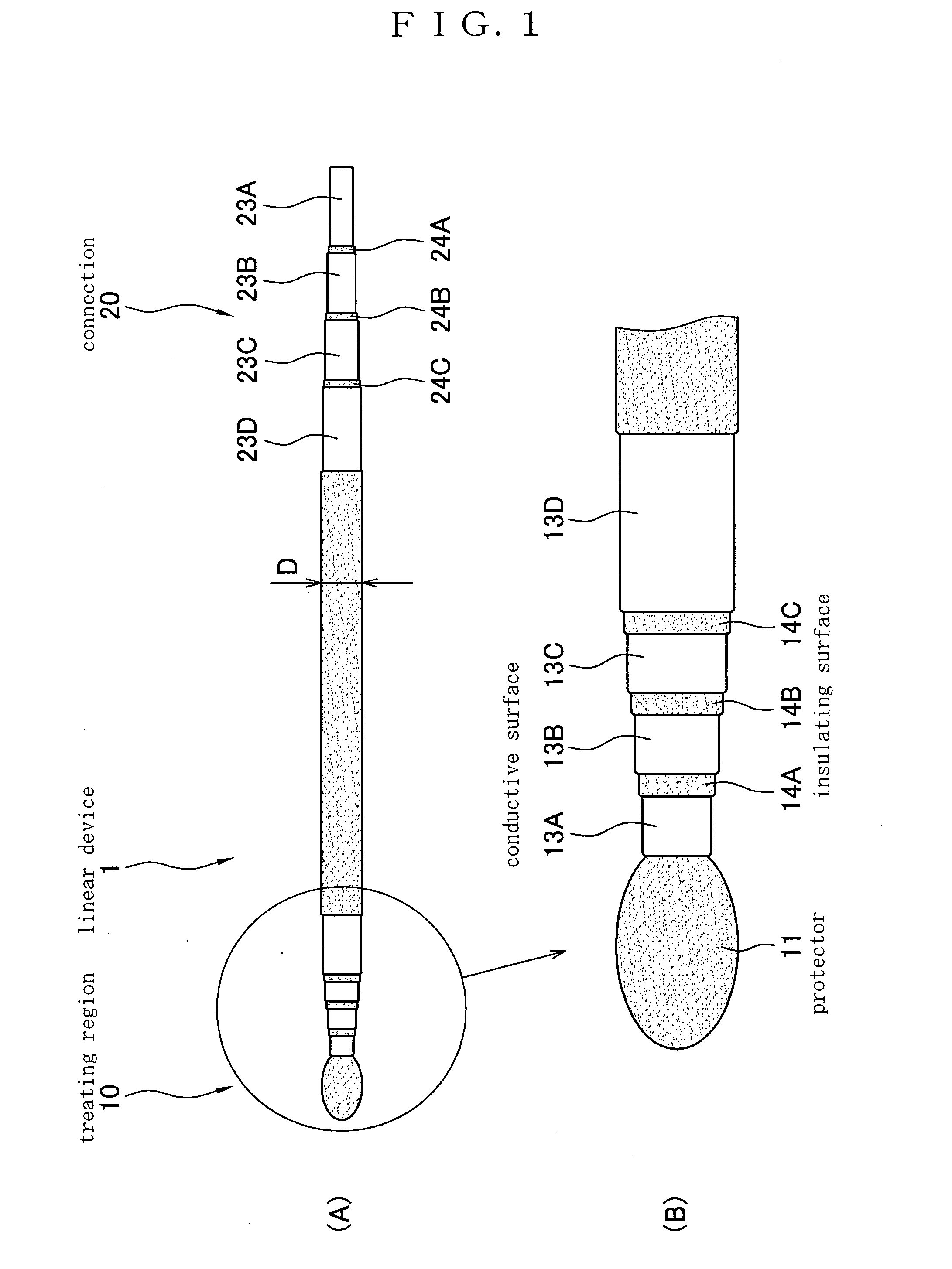
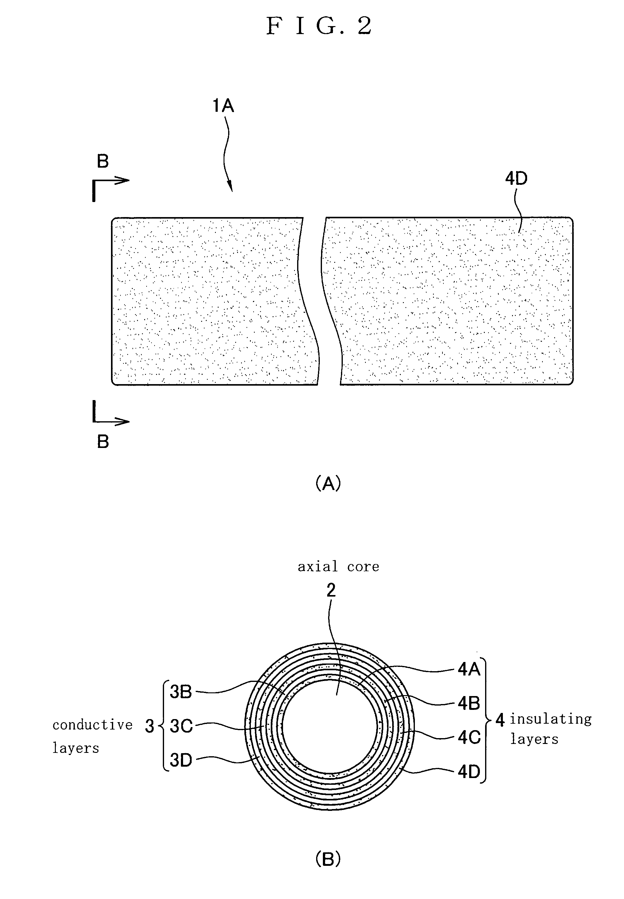
[0046]FIG. 1 is a schematic illustration of a linear device 1 with a treating region 10 in accordance with the present invention. FIG. 1 (A) is a side view of the linear device 1; FIG. 1 (B), an enlarged view of the treating region 10. FIG. 2 (A) is a side view of a linear device 1A without a treating region 10; FIG. 2 (B), an end view taken along the arrowed line B-B of FIG. 2 (A). As shown in FIGS. 1 and 2, the linear device 1 is a linear member comprising a plurality of layers of an insulating material and a plurality of layers of a conductive material.

[0047] As shown in FIG. 2 (B), the linear device 1 further comprises a rod-like member 2 (hereinafter referred to as “axial core”). The axial core 2 is of a conducting material and has a circular cross section.

[0048] A plurality of thin layers are formed on the axial core 2. The layers are insulating layers 4A-D of an insu...


PUM

PropertyMeasurementUnit
widthaaaaaaaaaa
diameteraaaaaaaaaa
diameteraaaaaaaaaa

Abstract

The object of the present invention is to provide a linear device which is very thin, can be inserted into a desired region of a subject, and minimizes the damage to the subject. The linear device is a linear member, which comprises a base layer extending in the axial directions of the linear member and a plurality of layers formed on the base layer and extending in the axial directions of the linear member. Two or more of said plurality of layers are conductive layers and two or more of said plurality of layers are insulating layers. Each insulating layer is disposed between the conductive layers. When the linear device is embedded in or its front end is inserted into a region of a subject, electric stimuli can be given to the region and the electric resistance of the region can be measured. Because the linear device is very thin, pain or uncomfortable feeling at the region is slight when it is inserted or embedded in a region of the human body or the like.

Description

TECHNICAL FIELD [0001] This invention relates to a linear device. More specifically, this invention relates to a linear device which is applied to or embedded in various regions of organisms or the like, give electric, thermal, or optical stimuli to the regions, and detect and measure the changes occurring in the regions electrically, electrochemically, or optically. BACKGROUND ART [0002] Enzyme sensors with enzyme-applied electrodes have been used to date to measure the density of sugar, amino acid, etc. in organisms. Enzymes oxidize and deoxidize sugar, amino acid, etc. selectively to generate molecules and ions, and enzyme sensors detect the quantity of such molecules and ions as the values of currents passing through their electrodes to determine the density of sugar, amino acid, etc. [0003] A glucose sensor is disclosed in the Japanese Unexamined Patent Publication No. 1993-60722 (hereinafter “Prior Art 1”). Another glucose sensor is disclosed in the literature “A new amperomet...

Claims


Application Information

Patent Timeline
Patent Type & Authority Applications(United States)
IPC IPC(8): A61B5/05A61N1/00A61B5/04A61N1/04G01N27/30A61B5/296A61N1/05
CPCA61B5/04001A61N1/05A61B2562/0215A61B5/24
Inventor YASUZAWA, MIKITOIMAI, SHINJI
Owner YASUZAWA MIKITO
Learn More