Magnetic resonance imaging apparatus

a magnetic resonance imaging and apparatus technology, applied in the field of magnetic resonance imaging apparatus, can solve the problems of low signal intensity for imaging data acquisition, degenerate image quality, and development of motion artifacts, and achieve the effect of improving image contrast and hence image quality

Inactive Publication Date: 2007-04-19
GE MEDICAL SYST GLOBAL TECH CO LLC
View PDF24 Cites 28 Cited by
  • Summary
  • Abstract
  • Description
  • Claims
  • Application Information

AI Technical Summary

Benefits of technology

[0013] According to the present invention, there is provided a magnetic resonance im

Problems solved by technology

In such imaging on a subject using the magnetic resonance imaging apparatus, if the subject moves during the scan, motion artifacts may appear in a produced slice image.
For example, when the heart or abdomen of the subject is imaged, body motion such as respiratory or cardiac motion leads to development of motion artifacts and degenerates image quality.
When imaging data is acquired while generating an RF pulse in a cycle of one second in synchronization with cardiac

Method used


Image

  • Magnetic resonance imaging apparatus
  • Magnetic resonance imaging apparatus
  • Magnetic resonance imaging apparatus

Examples


Embodiment Construction

[0021] An exemplary embodiment of the present invention will now be described with reference to the accompanying drawings.

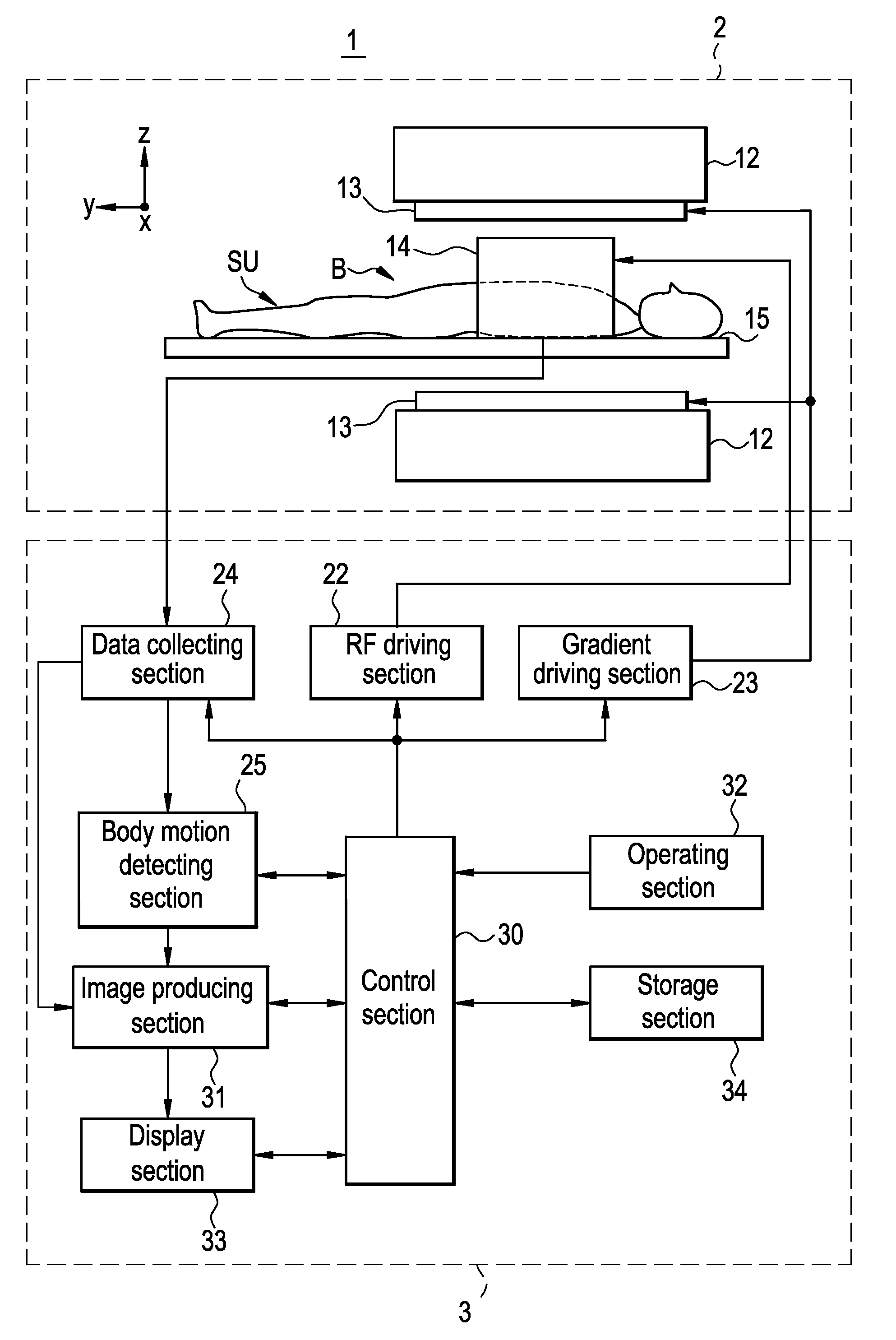
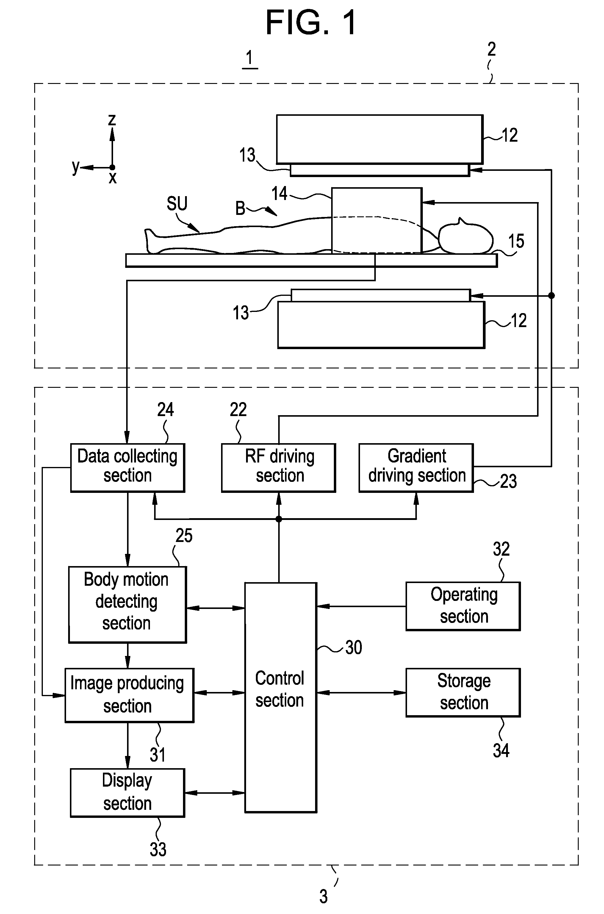
[0022]FIG. 1 is a block diagram showing the configuration of a magnetic resonance imaging apparatus 1 in an embodiment in accordance with the present invention.

[0023] As shown in FIG. 1, the magnetic resonance imaging apparatus 1 has a scanning section 2 and an operation console section 3.

[0024] Now the scanning section 2 will be described.

[0025] The scanning section 2 has a static magnetic field magnet section 12, a gradient coil section 13, an RF coil section 14, and a cradle 15, as shown in FIG. 1, for emitting an electromagnetic wave toward a subject SU to excite an imaged region in the subject SU in an imaging space B in which a static magnetic field is generated, and conducting a scan to acquire magnetic resonance signals generated in the imaged region in the subject SU.

[0026] In the present embodiment, the scanning section 2 repetitively scans the sub...


PUM


Abstract

For the purpose of improving contrast of an image, and hence, image quality, a navigator sequence NS for acquiring navigator echo data is performed before performing an imaging sequence IS each time, and a displacement N of the diaphragm caused by respiratory motion is detected based on the navigator echo data. Then, an imaging sequence IS for acquiring imaging data in the imaged region is performed if the detected displacement N caused by respiratory motion N of the subject falls within an acceptance window AW. Thereafter, each of a plurality of sets of imaging data acquired in the imaging sequence IS performed a plurality of number of times is corrected using a correction factor corresponding to a time interval between a first imaging sequence IS1 in which each set of imaging data is acquired and a second imaging sequence IS2 performed before the first imaging sequence IS1, and a slice image is produced from the plurality of corrected sets of imaging data.

Description

CROSS REFERENCE TO RELATED APPLICATIONS [0001] This application claims the benefit of Japanese Application No. 2005-304798 filed Oct. 19, 2005. BACKGROUND OF THE INVENTION [0002] The present invention relates to a magnetic resonance imaging apparatus, and particularly to a magnetic resonance imaging apparatus for emitting an electromagnetic wave toward a subject to excite an imaged region in the subject in a static magnetic field space, conducting a scan to acquire magnetic resonance signals generated in the imaged region in the subject, and then producing an image of the subject based on the magnetic resonance signals acquired by conducting the scan. [0003] Magnetic resonance imaging (MRI) apparatuses are widely used in various fields including a medical application and an industrial application. [0004] A magnetic resonance imaging apparatus emits an electromagnetic wave toward a subject in a static magnetic field space to thereby excite spins of protons in the subject with a nucle...

Claims


Application Information

Patent Timeline
IPC IPC(8): A61B5/05G01V3/00
CPCA61B5/055A61B5/7207G01R33/563G01R33/5635G01R33/56509G01R33/5673G01R33/5676G01R33/48
Inventor TAKEI, NAOYUKITSUKAMOTO, TETSUJI
Owner GE MEDICAL SYST GLOBAL TECH CO LLC
Why Eureka
Try Eureka