
Method and apparatuses for controlling high wing loaded parafoils

a parafoil and high-wing technology, applied in the field of parasail, can solve the problems of large and undesirable responses, high non-linear response to input control, spiraling descent, etc., and achieve the effect of removing noise and harmonic terms

Inactive Publication Date: 2007-04-19
ATAIR AEROSPACE +1
View PDF18 Cites 17 Cited by
  • Summary
  • Abstract
  • Description
  • Claims
  • Application Information

AI Technical Summary

Benefits of technology

[0011] According to another embodiment, the present invention features a stability augmentation (SAS) method. The SAS method includes receiving a heading rate command from a guidance system, receiving an actual heading rate (preferably from an attitude and heading reference system). The actual heading rate signal is preferably filtered to remove noise and harmonic terms. Next, the heading rate command and the actual heading ra...

Problems solved by technology

At very high wing-loads, however, the response to input control becomes highly non-linear.
Consequently, small input controls may result in large and undesirable responses.
This is particularly problematic and can result in a spiraling descent from which there is no recovery (an instability).
The difficulty in designing a SAS is that the nature of this nonlinearity (where it begins to happen and to what degree) is not known ahead of time because it depends on wing loading.
Moreover, even if the nonlinearity was known, designing the control system would still be difficult because the state of the art in control system design relies heavily on having a linear response.
Not doing this puts unneeded restrictions on users.
These restrictions will often not be adhered to, sacrificing accuracy and reliability.

Method used


Image

  • Method and apparatuses for controlling high wing loaded parafoils
  • Method and apparatuses for controlling high wing loaded parafoils
  • Method and apparatuses for controlling high wing loaded parafoils

Examples


Embodiment Construction

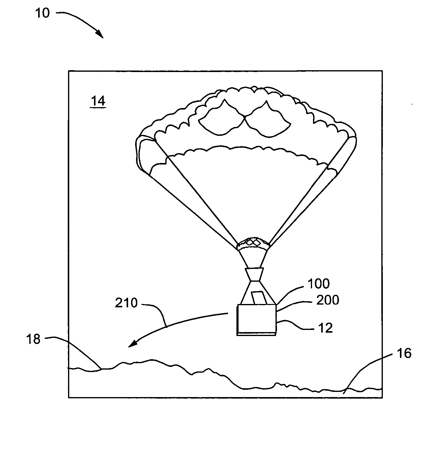
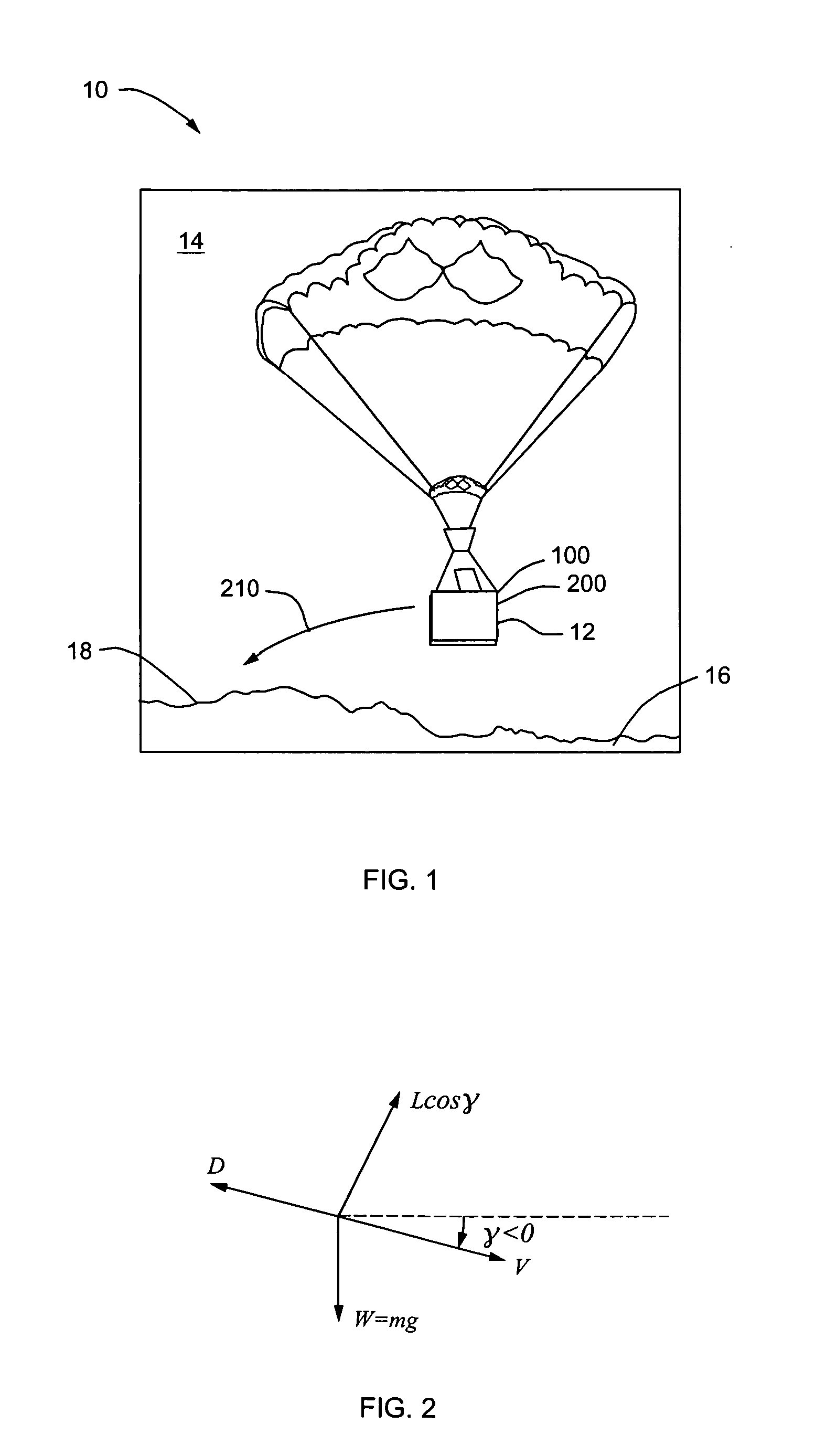
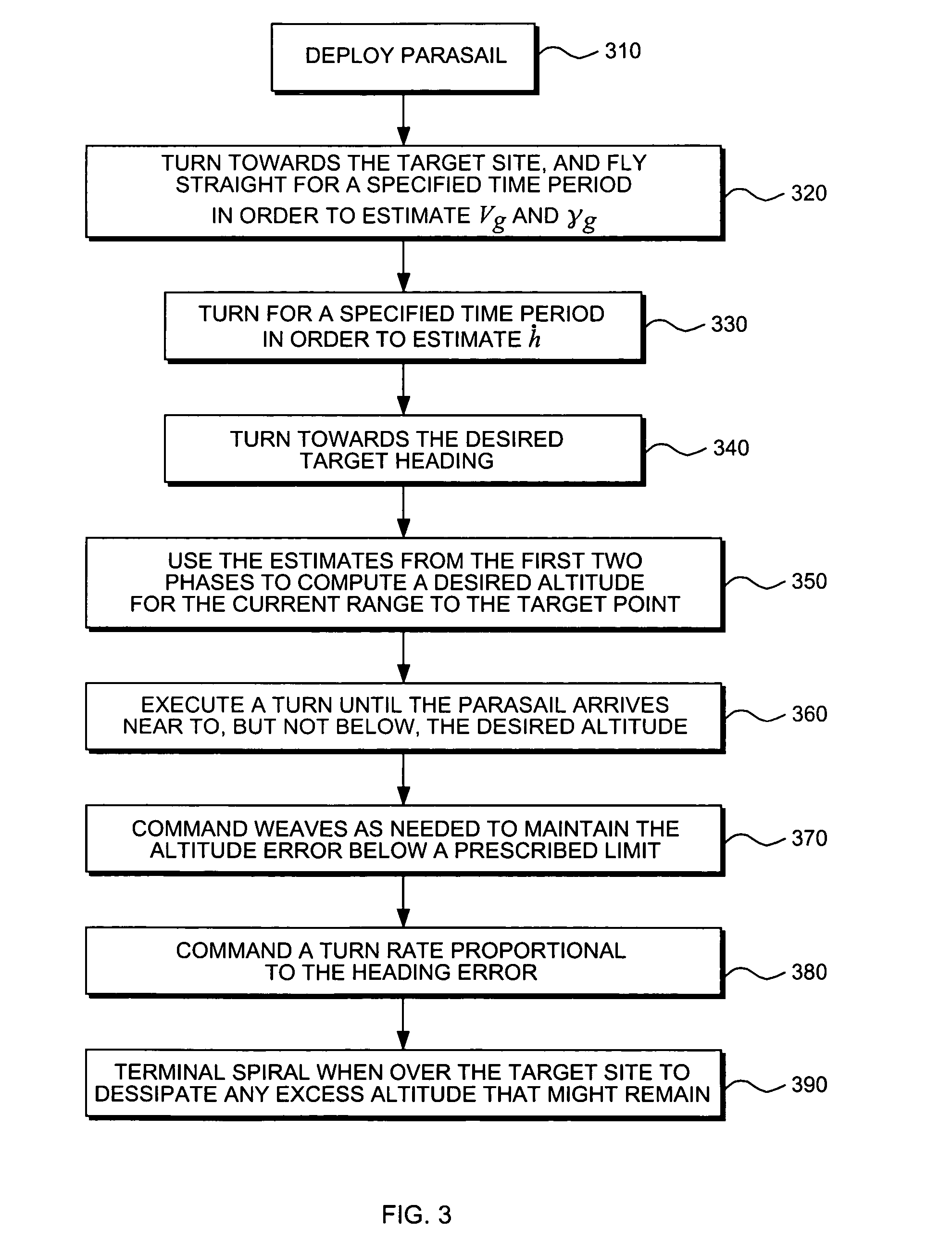
[0029] According to one embodiment, the present invention features an adaptive guidance system 100, FIG. 1, used in conjunction with a stability augmentation system (SAS) to control a parasail 10. The function of the adaptive guidance system 100 is to regulate the altitude and heading of a parasail 10 in such a way that it arrives at the target site 18 at a prescribed altitude (very similar to the problem of landing an aircraft) and to provide heading rate commands to the SAS 200 for execution. The altitude profile (altitude versus range to the target site) depends both on wing loading, and wind magnitude and direction, both of which may be unknown at the outset. Accordingly, the purpose of adaptive guidance system 100 is to ascertain (estimate) the glide slope and wind conditions on the fly, and to provide a command to the SAS 200 that will result in attaining the desired glide slope and heading 210.

[0030] As will be explained in greater detail hereinbelow, the guidance system 100...


PUM


Abstract

An adaptive guidance system (AGS) regulates the altitude and heading of a parasail to arrive at a target at a prescribed altitude. Since the altitude profile depends both on unknown wing loading, and wind magnitude and direction, the AGS estimates the glide slope and wind on the fly and provides a command to a stability augmentation system (SAS) that results in the desired glide slope and heading by performing a sequence of maneuvers and sensing the response. According to one embodiment, the SAS operates in the linear region and includes a PID controller that uses the difference between the actual heading and heading command to create an actuator output. The actuator output is limited by a position / rate limiter that imposes the physical limitations of the response time of the actuator / servos and position limits to prevent entering the nonlinear region. Alternatively, an adaptive SAS operates in both the linear and nonlinear region and includes a neural network (NN) that receives an error signal (difference between a reference model and actual heading) which is used to adapt the weights of the NN.

Description

CROSS-REFERENCE TO RELATED APPLICATIONS [0001] This application claims the benefit of U.S. Provisional Application Ser. No. 60 / 568,539, filed May 5, 2004.TECHNICAL FIELD [0002] The present invention relates to parasails and more particularly, relates to guidance and stability augmentation systems for use with guided parasails. BACKGROUND INFORMATION [0003] Guided parasails 10, FIG. 1, provide a means of achieving precision delivery of supplies 12 from air 14 to ground 16. Guided parasails 10 are often static line deployed from an aircraft (not shown) at altitudes up to approximately 35,000 feet. [0004] According to one embodiment, a guided parasail 10 includes a guidance system that outputs a heading rate command and a stability augmentation system (SAS) that follows (executes) that command. The guidance system typically includes an on-board flight computer that determines the position and heading of the parasail 10, usually based on a GPS and Inertial Navigation Sensors (INS) or th...

Claims


Application Information

Patent Timeline
IPC IPC(8): G01C23/00
CPCG05B13/042G05D1/105
Inventor PRESTON, DANIEL J.
Owner ATAIR AEROSPACE
Learn More