
Packaging device for free-flowing bulk material (filling)

Inactive Publication Date: 2007-04-26
POLY CLIP SYST
View PDF15 Cites 5 Cited by
  • Summary
  • Abstract
  • Description
  • Claims
  • Application Information

AI Technical Summary

Benefits of technology

[0010] The objective of the present invention is to create a device of the above-described type, but simpler in design and easier to handle.
[0029] In the first operating mode, the quasi-endless casing is moved over the first feeder tube segment and passes between rolling elements and feeder tube surface. The vertical orientation of the rolling element axes in relation to the longitudinal axis of the first feeder tube segment ensures that no frictional resistance at the rolling elements hinders the movement of the casing. In the second operating mode, a casing supply is manually loaded onto the second feeder tube segment from the feeder tube mouth so that the casing never comes in contact with the rolling elements. The rolling elements axes can therefore be oriented parallel to the longitudinal axis of the first feeder tube segment, and so the feeder tube rotation around the first longitudinal axis is almost without friction.

Problems solved by technology

Even today, casing is applied to the feeder tube in this way when it is not cost-effective to produce the casing continuously from plastic filmstrips, e.g. when using natural casing or when producing small quantities of sausages of variable caliber.

Method used


Image

  • Packaging device for free-flowing bulk material (filling)
  • Packaging device for free-flowing bulk material (filling)
  • Packaging device for free-flowing bulk material (filling)

Examples


Embodiment Construction

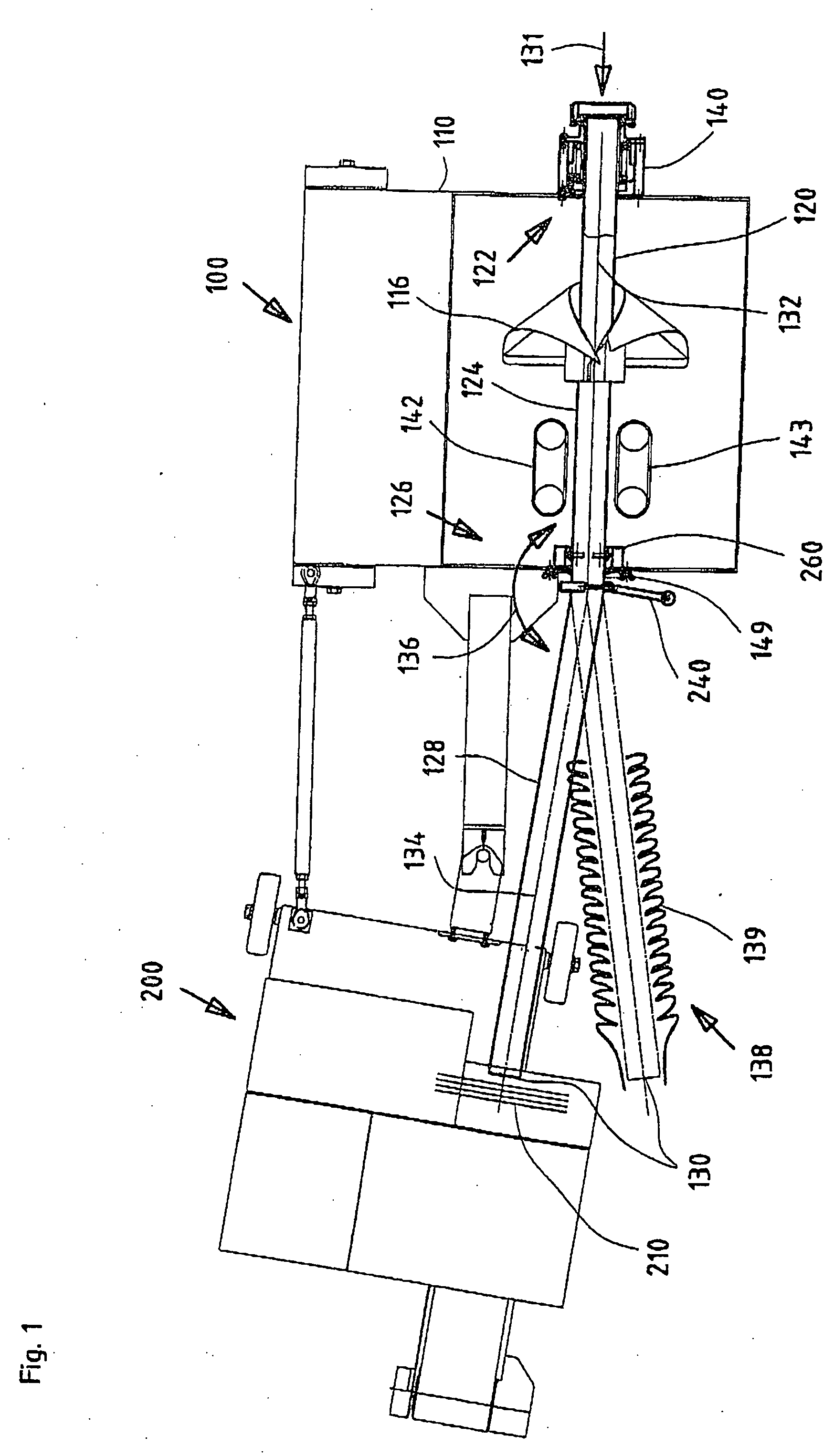
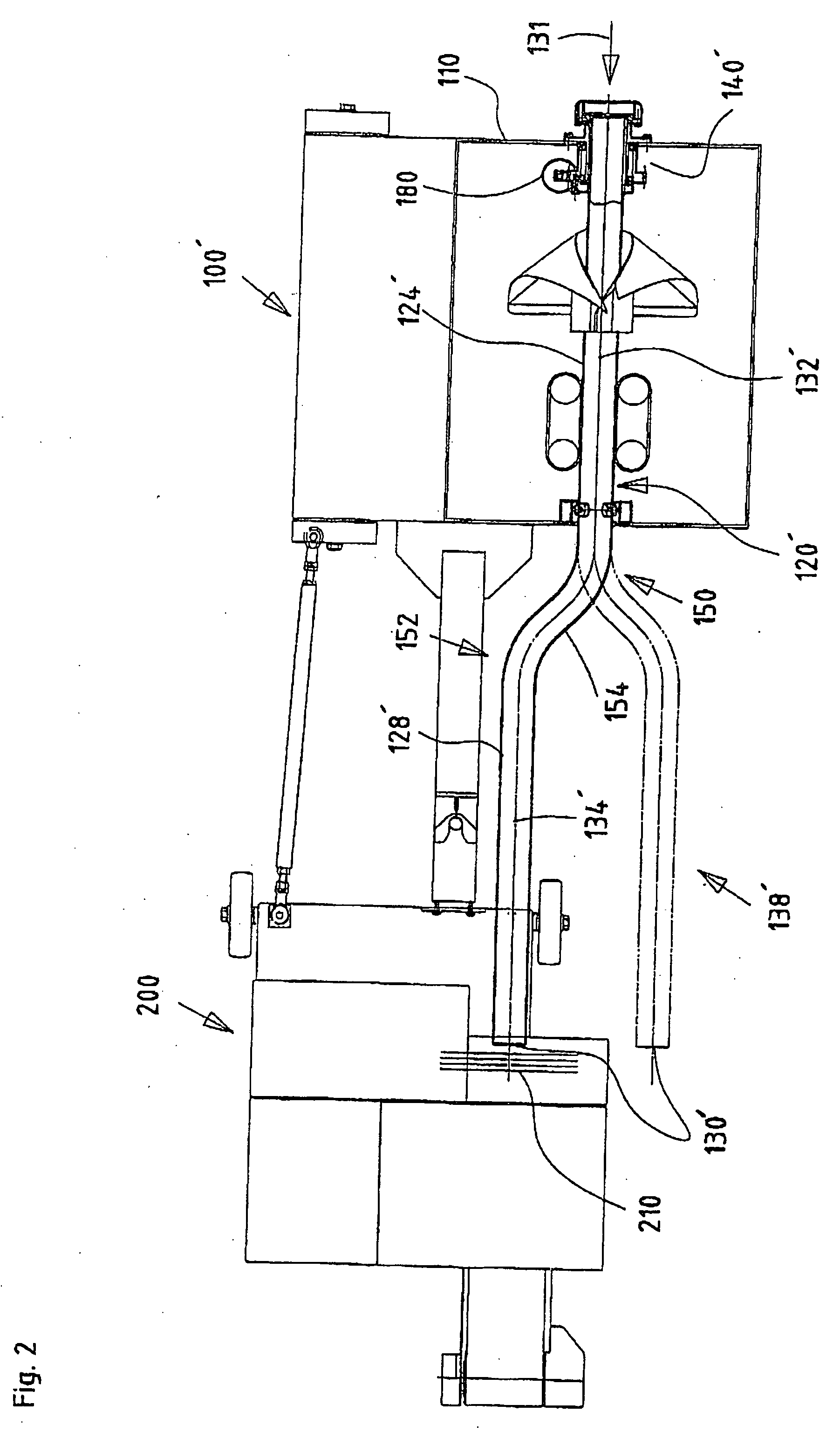
[0045] In the illustrations, components with identical function are labeled with identical numbers; modified components with predominantly similar functions are labeled with identical numbers followed by apostrophes.

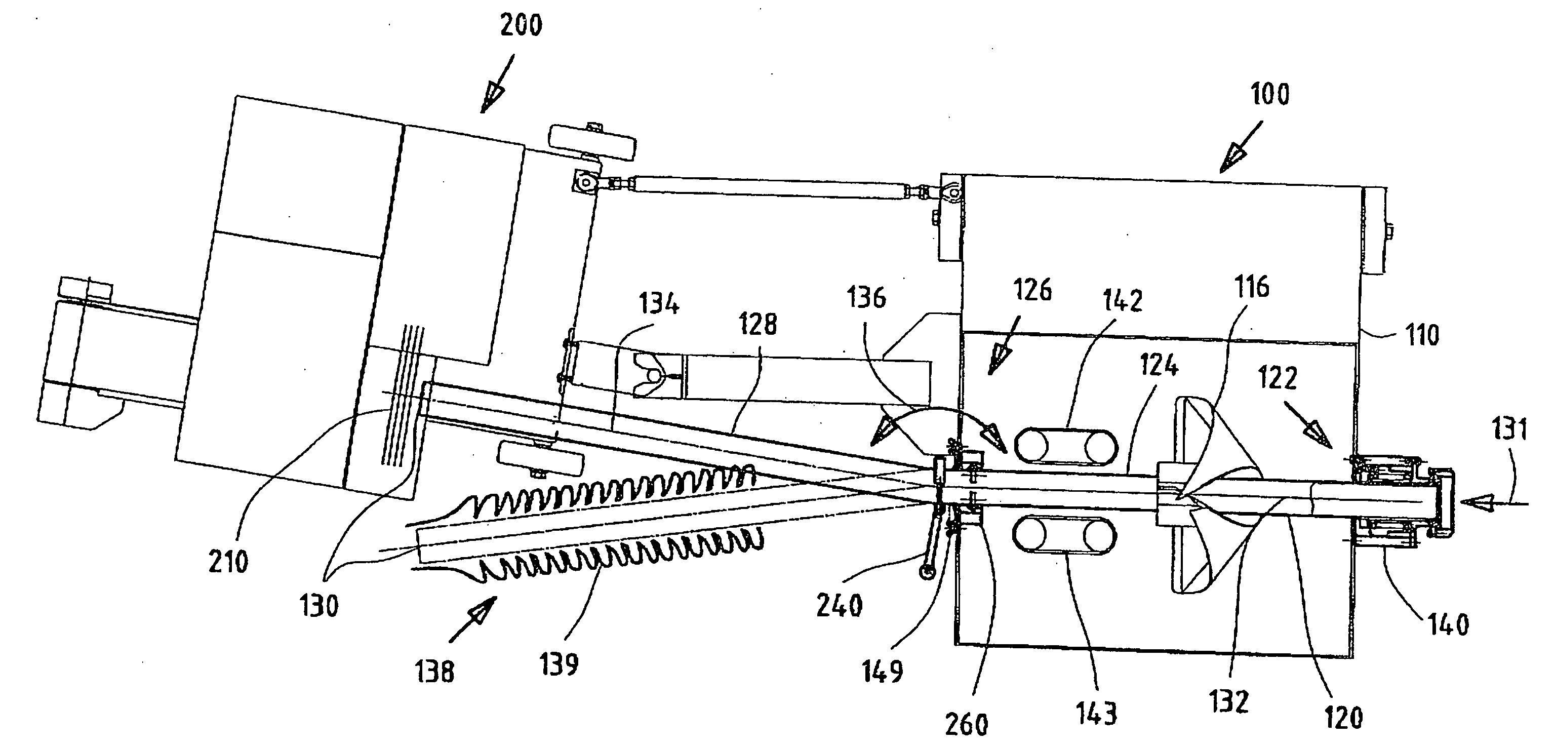
[0046]FIG. 1 shows in top view a system to package free-flowing fill materials in a tube-like casing. The system features device 100 according to the present invention and also shows downstream at the feeder tube mouth a closing unit 200, which partitions and seals the filled (sausage) casing.

[0047] The device 100 has a housing 110 for components, such as the sealing unit (not shown in this view), a forming unit or forming pad to transform a plastic film strip in a plastic film casing 118 as well as an infeed unit 142 that consists of two conveyor bands 142, 143 to advance the sealed plastic film casing 118 in automatic operating mode. Details for the sealing device follow below as part of the description to FIG. 2. The device 100 also includes a feeder tube 120 with a...


PUM

PropertyMeasurementUnit
Angleaaaaaaaaaa
Flow rateaaaaaaaaaa
Flexibilityaaaaaaaaaa

Abstract

The invention pertains to a device for the packaging of free-flowing fill materials in a tube-shaped casing with a feeder tubed to conduct the flow of fill materials. The feeder tube features a hookup, a mouth, a basically straight first segments adjoining the hookup, with a first longitudinal axis, and a second segment that is conjoined with the first segment and proximate to the mouth. The first segment is designed to accept and conduct a casing on its outer surface. The casing infeed consists of a plastic filmstrip, which is formed into a tube around the first feeder tube segment. The second segment is designed to further conduct the plastic filmstrip-derived, newly formed casing. Alternatively, a supply of casing and / or net material may be loaded onto the second segment from its mouth. Upstream and ahead of the first segment, the feeder tube features a feeder tube swivel bearing (140) around the first longitudinal axis. There is at least one change of feeder tube direction between the first and second segments.

Description

[0001] This application claims the benefit of German patent application serial number 10 2005 050 614.3, filed Oct. 21, 2005, and is hereby incorporated by reference. TECHNICAL FIELD [0002] The invention pertains to a packaging device for free-flowing bulk materials in a casing (a tube-like flexible covering). Part of the packaging device is a feeder tube, which attaches to the fill unit, and brings the stream of fill material from the fill unit to the closing unit for the casing. Feeder tube features are a hookup, a mouth, and a largely straight first segment with a first longitudinal axis next to the hookup and a second segment proximate to the mouth that conjoins with the first segment. The first feeder tube segment is designed to accept and conduct an infeed of plastic film and form it into a casing around its outer surface. The second feeder tube segment accepts and conducts the casing (derived from the plastic filmstrip) or alternatively, accepts and conducts a supply of casin...

Claims


Application Information

Patent Timeline
IPC IPC(8): B65B9/10
CPCA22C11/0209A22C11/0227B65B9/15
Inventor TOPFER, KLAUS
Owner POLY CLIP SYST
Learn More