Electronic lock box with key presence sensing

a technology of electronic lock box and key presence, which is applied in the direction of anti-theft devices, keyhole guards, program control, etc., can solve the problems of unsatisfactory determining whether the contents were returned and the key compartment secured, the contents of the lock box are not controlled, and the key will be lost, stolen or copied by unscrupulous peopl

Active Publication Date: 2007-04-26
SENTRILOCK
View PDF25 Cites 192 Cited by
  • Summary
  • Abstract
  • Description
  • Claims
  • Application Information

AI Technical Summary

Benefits of technology

[0006] Accordingly, it is an advantage of the present invention to provide an electronic lock box system used in real estate sales systems that provides a method of determining whether a key (or other object) was properly replaced into the secure compartment of the lock box. A further advantage is the ability to identify whether a dwelling key has been potentially been copied. Yet another advantage is to record for future review who accessed the lock box contents and whether they replaced the key (or other object), and further whether the person accessing the lock box properly closed the key compartment door.
[0007] Additional advantages and other novel features of the invention will be set forth in part in the description that follows and in part will become apparent to those skilled in the art upon examination of the following or may be learned with the practice of the invention.
[0008] To achieve the foregoing and other advantages, and in accordance with one aspect of the present invention, an electronic lock box system is provided, which comprises: an electronic lock box apparatus having a control circuit, a memory circuit, an identifier sensing device, a secure compartment with an access element, and a shackle for attachment to a fixed object, wherein the control circuit is configured to exchange data signals with the identifier sensing device; and a security apparatus having an identification member, and an attachment member; wherein: (a) the identifier sensing device detects a presence of the identification member of the security apparatus, if the security apparatus is positioned within the secure compartment; and (b) the identifier sensing device detects an absence of the identification member of the security apparatus, if the security apparatus is not positioned within the secure compartment.
[0009] In accordance with another aspect of the present invention, a security apparatus used with an electronic lock box system is provided, which comprises: (a) an identification member, which includes an identification control circuit, a memory circuit having alterable memory elements, a wireless transceiver, and at least one input / output circuit; and (b) an attachment member for use with an external key; (c) wherein: the identification control circuit is configured to perform at least one of the following functions: (i) to modify a data value of the alterable memory elements, in response to the attachment member becoming detached from the key; and (ii) to disable itself in response to the attachment member becoming detached from the key.
[0010] In accordance with yet another aspect of the present invention, a security apparatus used with an electronic lock box system is provided, which comprises: (a) an identification member, which comprises one of: (i) a bar code label; and (ii) an radio frequency identification (RFID) tag; (b) an attachment member for use with an external key; wherein the identification member becomes unreadable in response to the attachment member becoming detached from the external key.
[0011] In accordance with still another aspect of the present invention, an electronic lock box is provided, which comprises: an electronic lock box apparatus having a control circuit, a memory circuit, a secure compartment with an access element, and a shackle for attachment to a fixed object; and an access element sensing circuit that detects whether the secure compartment is in one of: (a) an open state; and (b) a closed state; wherein the control circuit is configured to exchange data signals with the access element sensing circuit.

Problems solved by technology

One challenge in previous designs has been the lack of control of the lock box contents.
Homeowners have expressed a concern that a key will be lost, stolen, or copied by an unscrupulous person.
Previous electronic lock box systems have addressed many aspects of logging the identity of who has accessed the contents (e.g., a key) of the lock box, but none has addressed the need for determining whether the contents were returned and the key compartment secured.

Method used


Image

  • Electronic lock box with key presence sensing
  • Electronic lock box with key presence sensing
  • Electronic lock box with key presence sensing

Examples


Embodiment Construction

[0025] Reference will now be made in detail to the present preferred embodiment of the invention, an example of which is illustrated in the accompanying drawings, wherein like numerals indicate the same elements throughout the views.

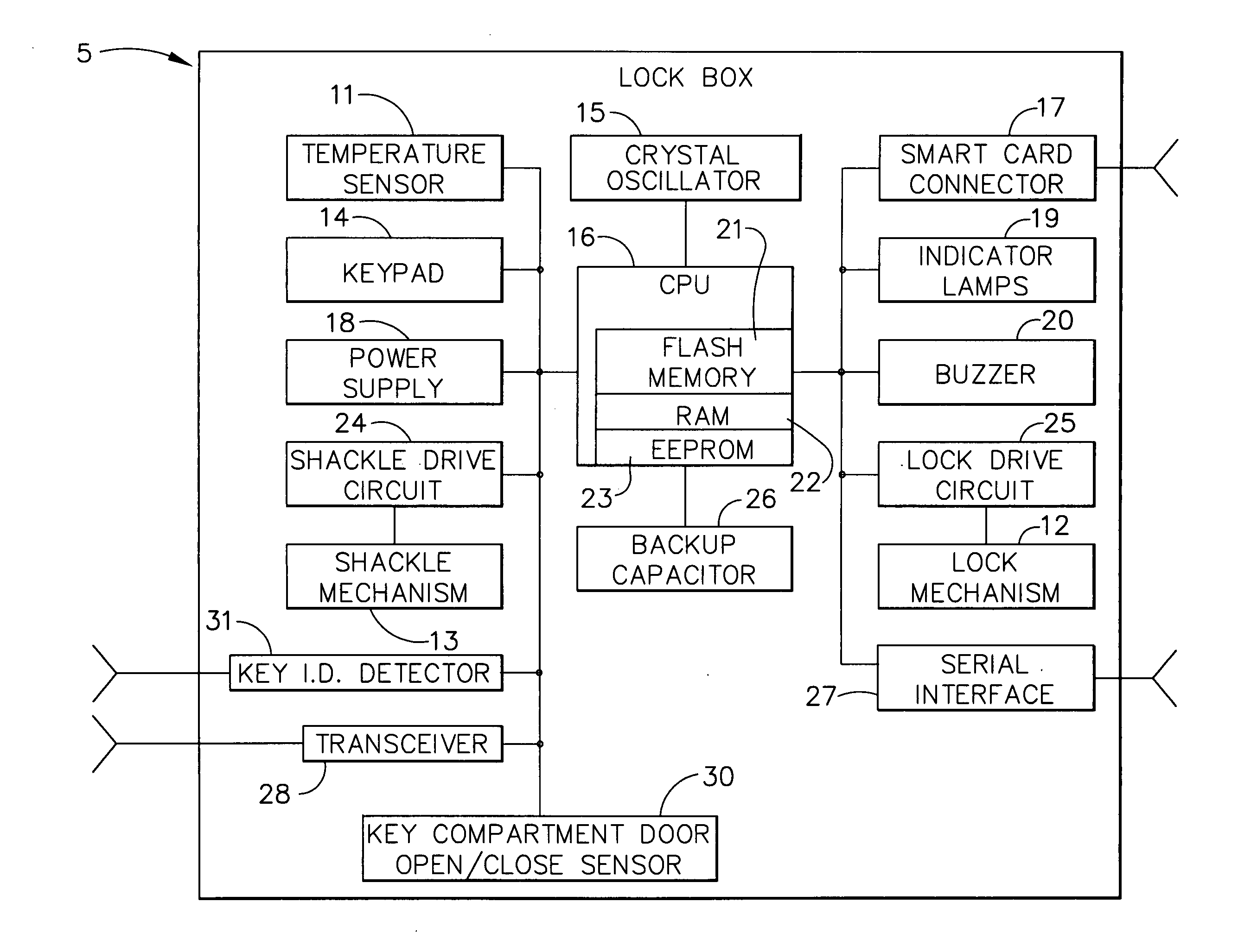
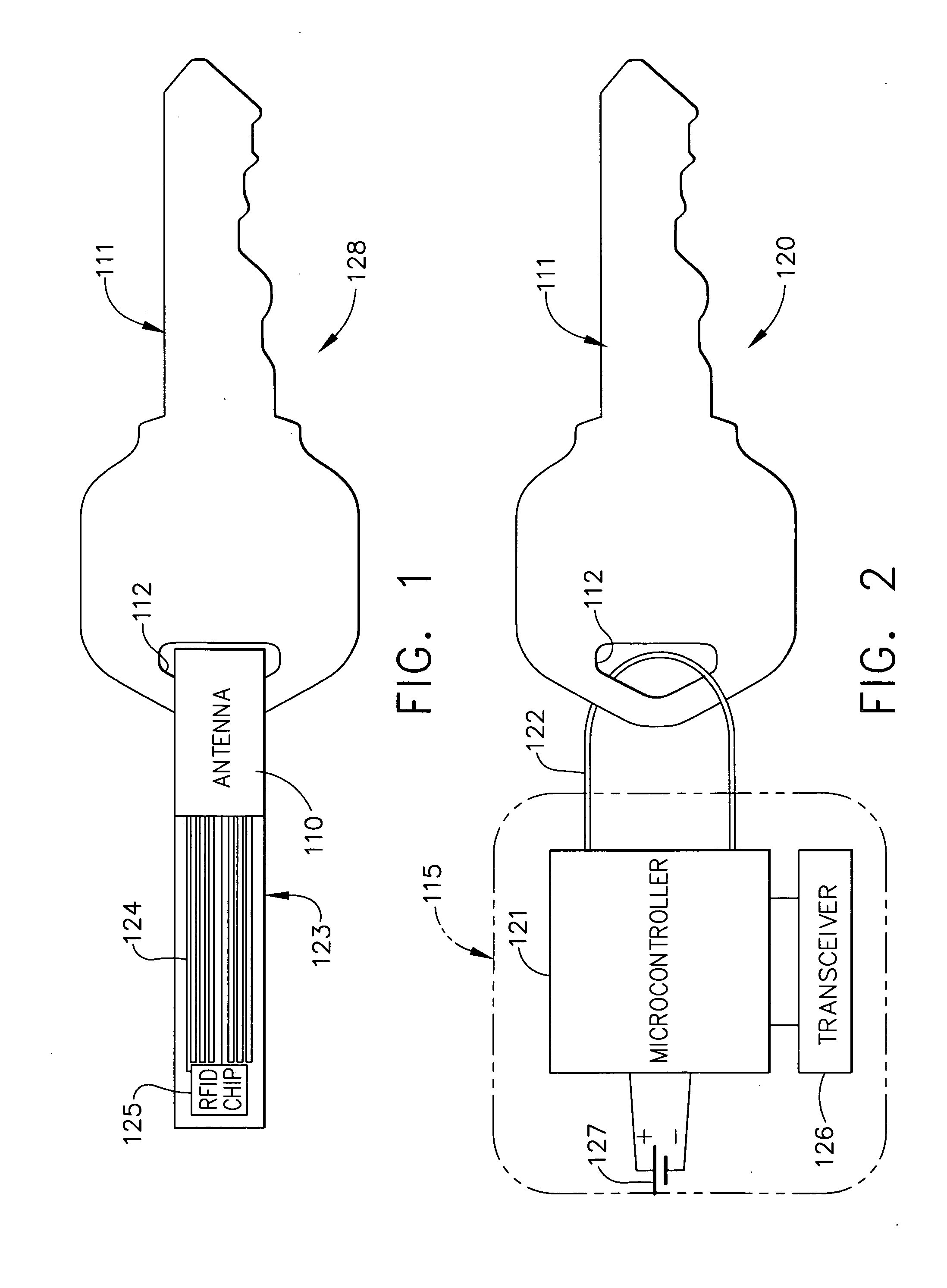
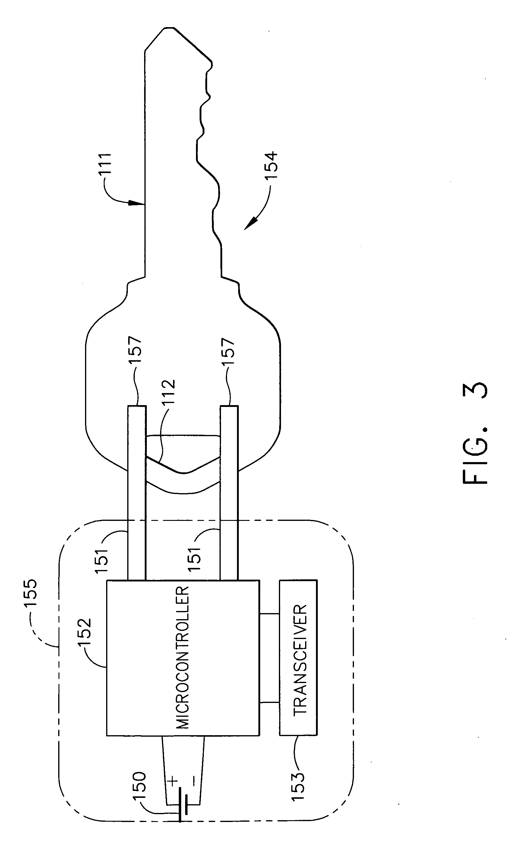
[0026] The present invention offers improvements to conventional electronic lock box systems, in which there are two main system components. The first main component is a specially designed “key security apparatus;” and the second main component provides additional sensors to the base (standard) lock box electronics, for communicating or retrieving data from the key security apparatus, as well as additional sensor elements to determine the key compartment's latching state.

[0027] Other aspects of the electronic lock box of the present invention are more fully described in earlier patents and patent applications by the same inventor, including Ser. No. 10 / 172,316, filed on Jun. 14, 2002, titled “ELECTRONIC LOCK SYSTEM AND METHOD FOR ITS USE,” now U.S. Pa...


PUM


Abstract

An electronic lock box contains a secure compartment for storing keys to a structure. A sensing system allow the lock box to determine whether the contents of the lock box have been replaced as well as ensuring the correct key or object has been returned. The system reports the status of the object back to the central clearinghouse computer through an electronic key or secure memory device.

Description

CROSS-REFERENCE TO RELATED APPLICATIONS [0001] The present application claims priority to provisional patent application Ser. No. 60 / 730,295, titled “ELECTRONIC LOCK BOX WITH KEY RETURN SENSING,” filed on Oct. 26, 2005.TECHNICAL FIELD [0002] The present invention relates generally to electronic lock equipment and is particularly directed to an electronic lock box of the type that contains a secure compartment for storing keys that allow entry to a building or other structure. The invention is specifically disclosed in as an electronic lock box that includes sensors which can determine whether a mechanical key is present within the secure compartment, which also allows the electronic lock box to determine if the user of the contents (e.g., a mechanical key) of the lock box returns the key to the secure compartment of the lock box, prior to closing the secure compartment's door. BACKGROUND OF THE INVENTION [0003] In the real estate industry, a need exists for controlled access to home...

Claims


Application Information

Patent Timeline
Patent Type & Authority Applications(United States)
IPC IPC(8): B60R25/00
CPCG07C9/00103G07C9/00309G07C9/00563G07C9/00896G07C2009/00936G07C9/27Y10T70/446Y10T70/5031Y10T70/7915Y10T70/8216
Inventor FISHER, SCOTT R.
Owner SENTRILOCK
Why Eureka
Try Eureka