Absolute velocity measuring device

a technology of absolute velocity and measuring device, which is applied in the direction of instruments, antenna details, antennas, etc., can solve the problems of insufficient contribution to the reduction in size and cost of the device, complicated and difficult adjustment of the axis, and large device size and cost, so as to reduce the restriction on the place where the device is installed to the car body, the effect of absolute velocity

Inactive Publication Date: 2007-04-26
HITACHI LTD
View PDF28 Cites 14 Cited by
  • Summary
  • Abstract
  • Description
  • Claims
  • Application Information

AI Technical Summary

Benefits of technology

[0008] According to embodiments of the invention, a plurality of kinds of information among velocity in a back and forth direction, velocity in a left and right direction, magnitude of velocity, a moving direction, a pitch angle, and a roll angle of a vehicle can be obtained by a set of transmission and reception functions, and consequently an absolute velocity measuring device can be reduced in size and cost compared with a ca

Problems solved by technology

In a configuration of the technique, since a set of transmission circuit and a reception circuit are provided for each of directions to be measured, there is a difficulty that a device becomes large and expensive.
While an oscillator is shared by the two Doppler sensors in the related art, even if only the relevant portion is shared, contribution to reduction in size and cost of the device is not sufficient.
More

Method used


Image

  • Absolute velocity measuring device
  • Absolute velocity measuring device
  • Absolute velocity measuring device

Examples


Embodiment Construction

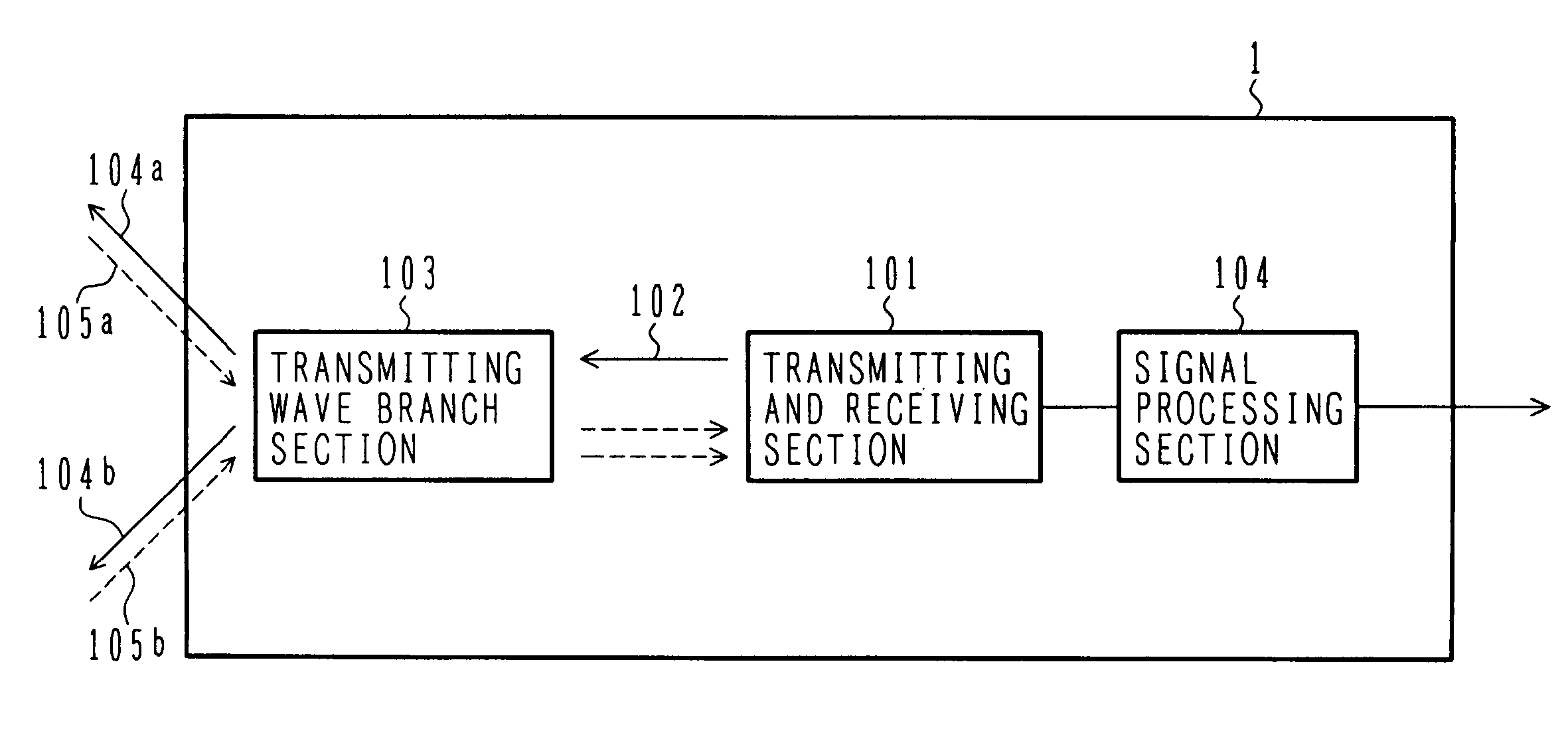
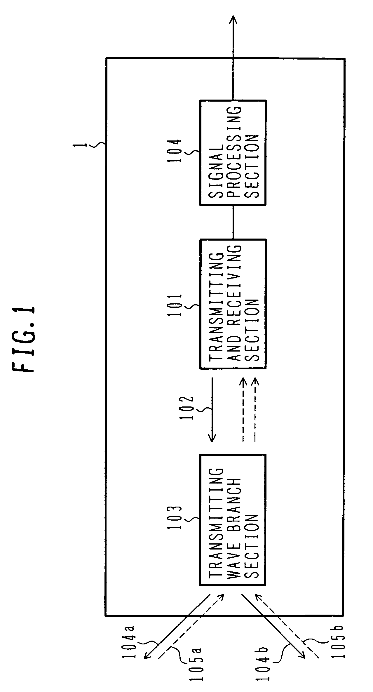
[0028]FIG. 1 is a block diagram of an absolute velocity measuring device of an embodiment of the invention. While the device is called absolute velocity measuring device here, it may be called absolute vehicle velocity sensor, ground vehicle velocity sensor, ground velocity sensor, vehicle behavior detection device, or the like.

[0029] The absolute velocity measuring device 1 in FIG. 1 includes a transmitting and receiving section 101, transmission wave branch section 103, and signal processing section 104. The transmitting and receiving section 101 transmits a unidirectional wave (light, an electromagnetic wave, sound and the like, which have properties as awave) (102), and a transmitted wave is branched in a plurality of directions (in the figure, an example of two directions is shown) by the transmission wave branch section 103, and then transmitted to a road surface (104a, 104b). Transmitted waves are reflected on the ground, and reflected waves 105a, 105b that have been reflect...


PUM


Abstract

In a configuration of a technique in the related art, since two Doppler sensors are used to measure velocity in two directions, and a set of transmission circuit and reception circuit are provided for each of directions to be measured, a device becomes large and expensive. Moreover, in the related art, since signal processing is performed by using output of each of the two Doppler sensors, axis adjustment in each of emission directions of the two Doppler sensors needs to be performed separately, therefore there is a difficulty that appropriate axis adjustment is complicated and difficult. An absolute velocity measuring device is mounted in a vehicle, and includes a transceiver for transmitting and receiving a wave, a transmission-wave branch section that branches a unidirectional wave transmitted from the transceiver in a plurality of directions, and converges reflected waves of waves branched in the plurality of directions from the ground into the unidirectional wave to be received by the transceiver, and a signal processing section that obtains a signal based on a reflected wave that has been received from the transceiver, and processes the obtained signal and thus calculates a plurality of kinds of behavioral information of the vehicle, and then outputs the relevant behavioral information.

Description

BACKGROUND OF THE INVENTION [0001] 1. Field of the Invention [0002] The present invention relates to an absolute velocity measuring device. [0003] 2. Description of the Related Art [0004] A technique of measuring a moving direction and magnitude of velocity of a vehicle using two Doppler sensors is known (for example, JP-A-10-20027). In the technique, two Doppler sensors are used to transmit and receive an electromagnetic wave with respect to two different vehicle-travel-surfaces in a horizontal direction. Based on Doppler signals outputted from the two Doppler sensors respectively, velocity in each of radio emission directions is calculated. Velocity components in the two directions are vector-synthesized, thereby the moving direction and the magnitude of velocity of the vehicle are measured. In the technique, polarized waves of transmission waves are in a relationship of being perpendicular to each other in order to reduce effects of crosstalk when electromagnetic waves having the...

Claims


Application Information

Patent Timeline
IPC IPC(8): G01S13/58G01S13/60
CPCG01S13/589G01S13/60H01Q1/3233
Inventor YOSHIKAWA, TOKUJIKURODA, HIROSHIKURAGAKI, SATORUNAGASAKU, TOSHIYUKI
Owner HITACHI LTD
Why Eureka
Try Eureka