Panel type television and LCD television

a technology for lcd televisions and panels, applied in the field of wall mount structures and panel securing plate structures, can solve the problems of difficult to achieve cost reduction, difficult to mount a display panel with a plate, etc., and achieve the effect of sufficient strength and easy fixing of substrates

Inactive Publication Date: 2007-04-26
FUNAI ELECTRIC CO LTD
View PDF17 Cites 34 Cited by
  • Summary
  • Abstract
  • Description
  • Claims
  • Application Information

AI Technical Summary

Benefits of technology

[0028] In this aspect configured as described above, it is possible to obtain sufficient strength by bending a sheet metal even if a thinner sheet metal is used, and also make it easier to fix substrates to the substrate fixing member by narrowing the longitudinal width.

Problems solved by technology

However, unlike a CRT, the size and fixing method of a display panel differs with the manufacturer, and therefore it is difficult to mount a display panel with a plate as described above, and a display panel-specific plate part is needed.
Moreover, since a plate part for a large sized display panel must also be large in size, and a few manufacturers have a machine to work plate parts, it is difficult to achieve cost reduction.
In addition, the larger a plate part, the heavier its weight, making it disadvantageous in special tests such as drop test and vibration test.

Method used


Image

  • Panel type television and LCD television
  • Panel type television and LCD television
  • Panel type television and LCD television

Examples


Embodiment Construction

[0043] The detailed description set forth below in connection with the appended drawings is intended as a description of presently preferred embodiments of the invention and is not intended to represent the only forms in which the present invention may be constructed and or utilized.

Preferred embodiments of the present invention are described below in the following order:

1. The configuration of a panel type television according to the present invention

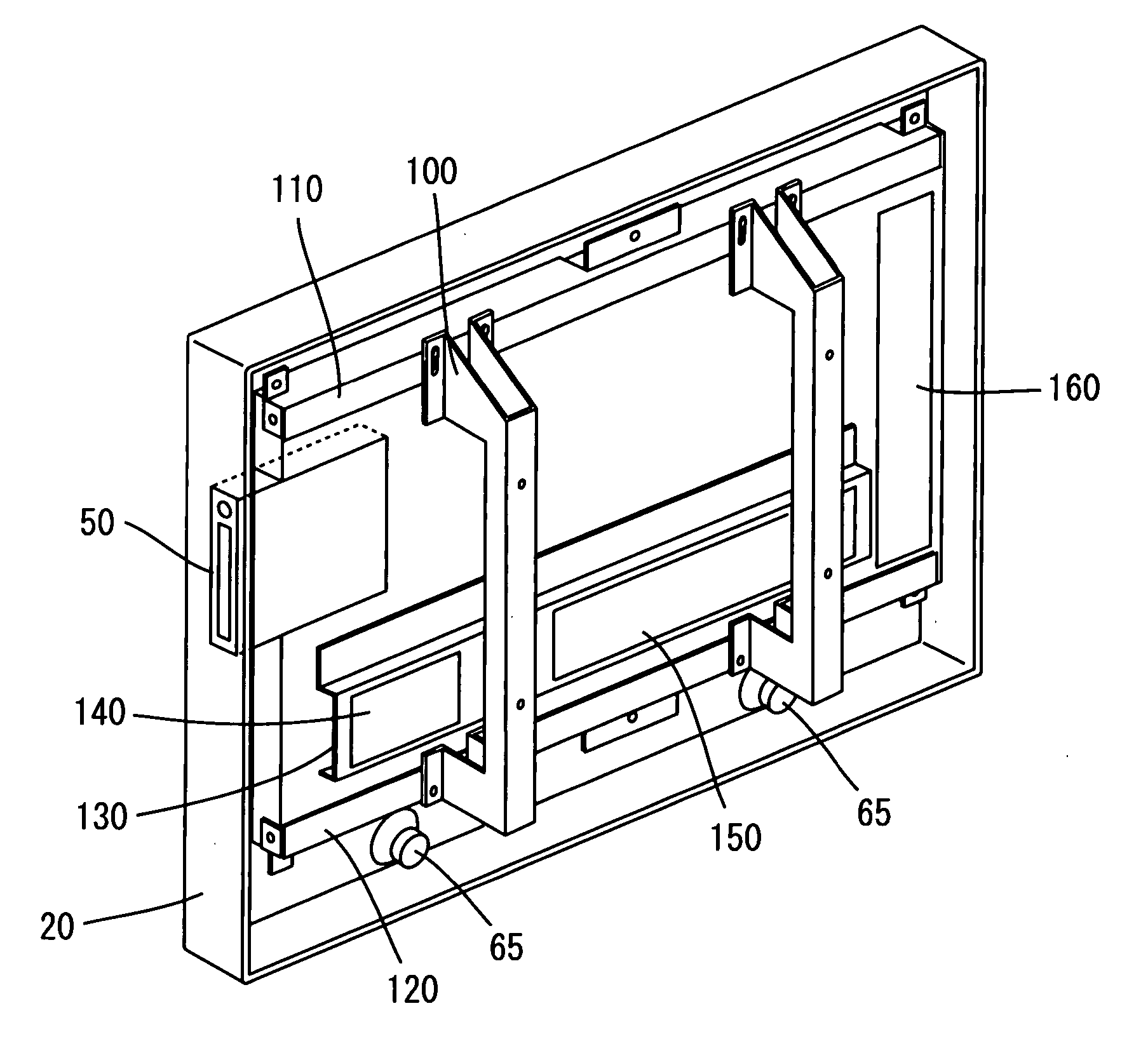
2. The structure and advantages of a panel fixing plate

3. Summary

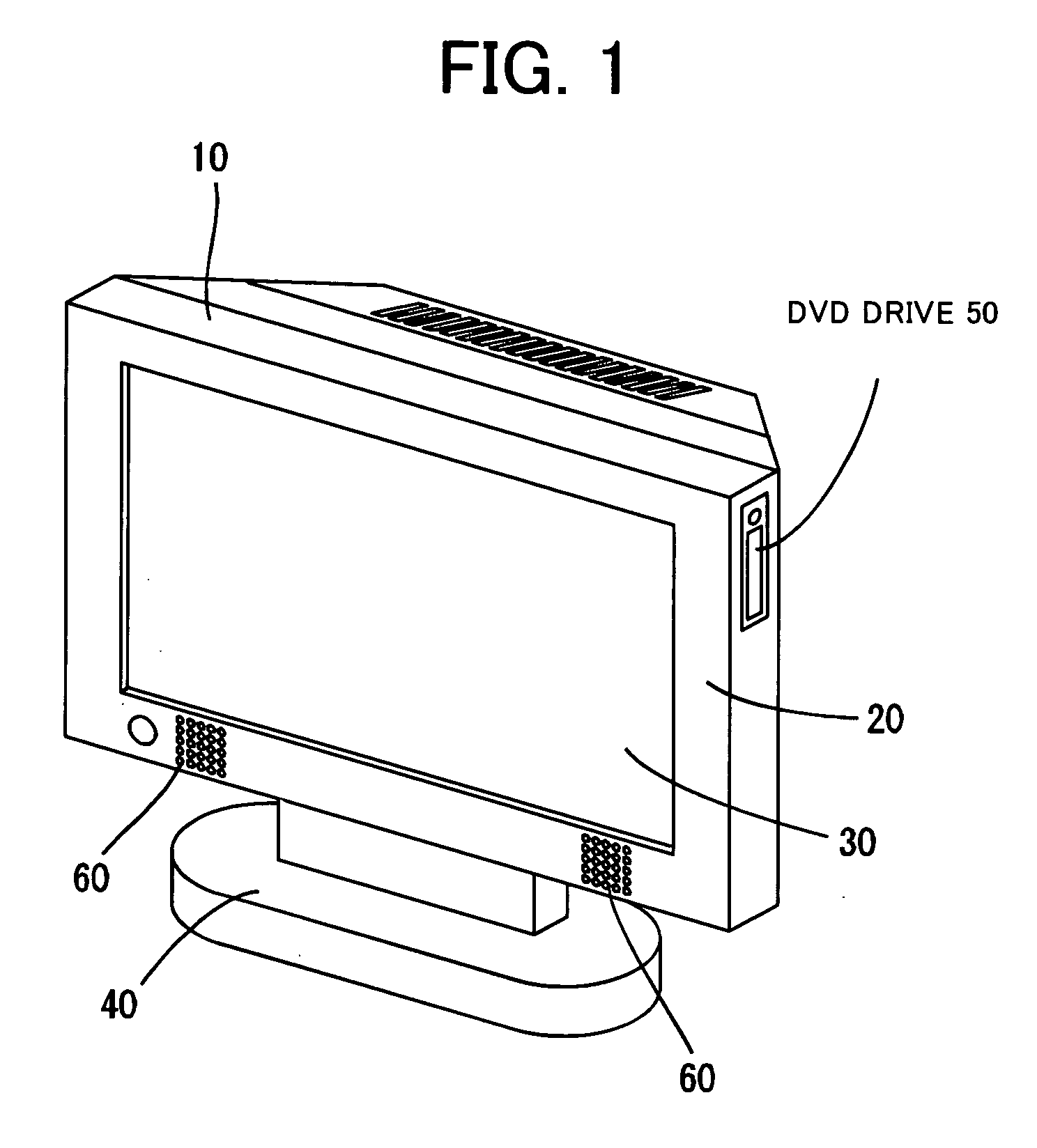
[0044] 1. FIG. 1 is a front perspective view of a panel type television. In this figure, a panel type television 10 is composed of a cabinet 20, an LCD panel 30 to display pictures on the screen, and a leg 40. The cabinet 20 holds the LCD panel 30 so that its display surface is exposed toward the front of the panel type television 10. The leg 40 supports the cabinet 20 and thereby holds the display surface of the LCD panel 30 in a rough vertical position.

[0045] ...


PUM

PropertyMeasurementUnit
sizeaaaaaaaaaa
sizeaaaaaaaaaa
thicknessaaaaaaaaaa

Abstract

Since size and mounting method of display panels of a large-sized panel type television differ by manufacturers, different parts are needed for display panels of different manufacturers. The display panel fixing plate is separated into a panel top fixing plate, a panel bottom fixing plate, and a bridge plate. The panel top fixing plate is fixed to the upper side of a flat display panel and the panel bottom fixing plate to the lower side of the flat display panel, and both plates are held with two bridge members. In addition, by making a screw hole vertically oblong that is used for screwing the bridge member to the panel top fixing plate, it is possible use the same panel top fixing plate, the panel bottom fixing plate, and the bridge plate for different inch display panels.

Description

CROSS-REFERENCES TO RELATED APPLICATIONS [0001] The present application is related to the Japanese Utility Model Application No. 2005-008747, filed Oct. 21, 2005, the entire disclosure of which is expressly incorporated by reference herein. BACKGROUND OF THE INVENTION [0002] (1) Field of the Invention [0003] The present invention relates to a wall mount structure and a panel securing plate structure for a panel type television such as an LCD television and a plasma type television. [0004] (2) Description of Related Art [0005] The flat display panel of a panel type television is mounted on the front panel from behind by means of a plate. For a large-sized panel type television, in particular, a display panel is mounted on the front cabinet by means of a plate that covers the entire display panel from behind. [0006] Furthermore, since a panel type television is often used by hanging it on a wall, as well as standing it upright, for a small sized panel type television which is relative...

Claims


Application Information

Patent Timeline
Patent Type & Authority Applications(United States)
IPC IPC(8): G02F1/1333
CPCH04N5/64
Inventor MARUTA, NAOTOYOKAWA, AKIRA
Owner FUNAI ELECTRIC CO LTD
Why Eureka
Try Eureka