
Method and system for increasing holographic data storage capacity using irradiance-tailoring element

a technology of irradiance and holographic data, applied in the field of method and system for increasing holographic data storage capacity using irradiancetailoring element, can solve the problems of detriment to high-fidelity holographic recording, distortion of recording medium, negative and dramatic impact on the available storage capacity of holographic recording medium

Inactive Publication Date: 2007-04-26
AKONIA HOLOGRAPHICS
View PDF39 Cites 21 Cited by
  • Summary
  • Abstract
  • Description
  • Claims
  • Application Information

AI Technical Summary

Benefits of technology

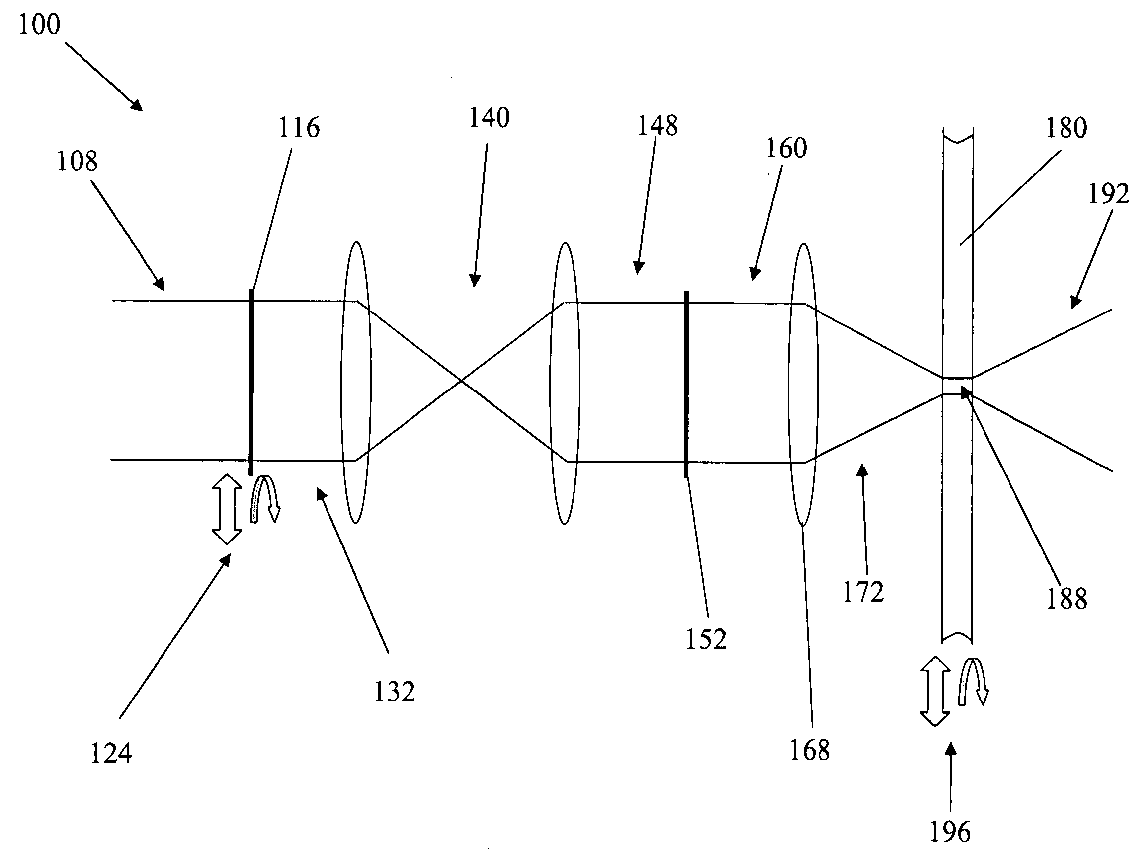
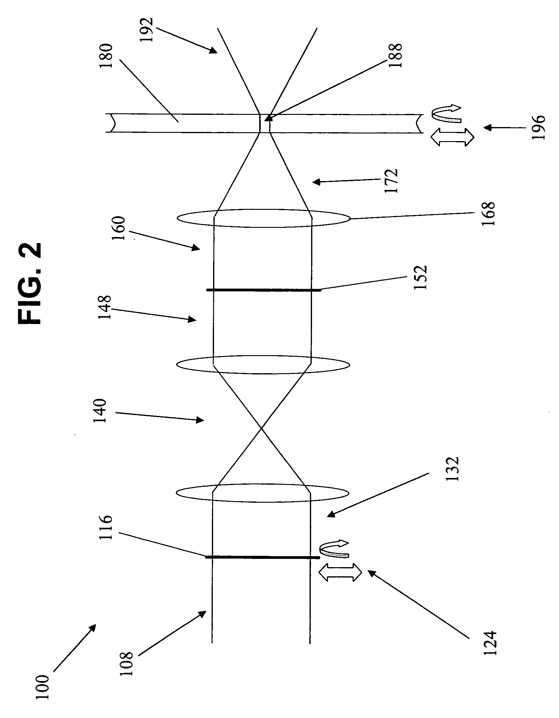
[0024] (2) changing the irradiance profile of the modulated data beam to thereby minimize the effects of fixed-pattern noise buildup from occurring in a holographic recording medium.
[0028] (3) changing the irradiance profile of the relayed modulated data beam after forming the at least one hologram to thereby minimize the effects of fixed-pattern noise buildup from occurring in the holographic recording medium.
[0033] means for changing the irradiance profile of the modulated data beam to thereby minimize the effects of fixed-pattern noise buildup from occurring in a holographic recording medium.
[0040] means for changing the irradiance profile of the relayed data beam after forming the at least one hologram to thereby minimize the effects of fixed-pattern noise buildup from occurring in the holographic recording medium.

Problems solved by technology

First, the volume of the holographic recording medium required for the data and reference signal beams to interfere determines the number of discrete optical recording sectors allowed across the surface of a given area of the medium.
The undesired side-effect of using a focused beam centered in the volume of the holographic recording medium is that local areas of extremely high energy irradiance are created, which in turn over-expose and distort the recording medium, to the detriment of high-fidelity holographic recording.
), issued Mar. 10, 1998, which use stationary or fixed “phase masks.” All of these methods may negatively and dramatically impact the available storage capacity of the holographic recording medium.
There have been very few methods developed to decrease this DC hot spot effect.
Because of the difficulty in aligning a pixel matched phase mask to an amplitude (data) modulator, the practicality of using such a phase mask is questionable.
These discontinuities are difficult to manufacture and may also result in a potential loss of data when the discontinuity occurs in the middle of a pixel.
Instead, the axicon causes the DC component of the irradiance profile to become donut shaped, which is not an ideal way to smooth the irradiance profile in the focus plane.
However, the phase pixels in both these masks have the same alignment, registration and interference difficulties as the two and multiple level masks.
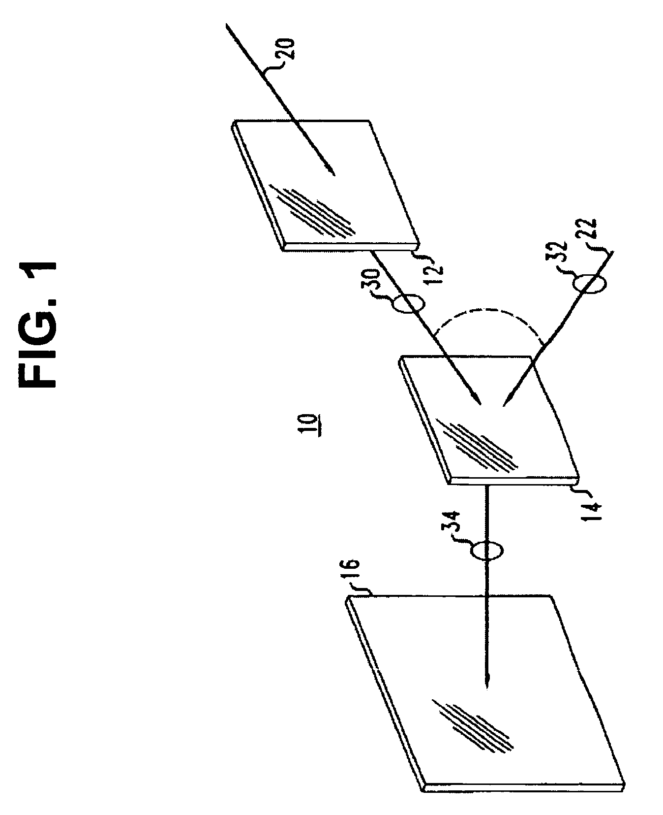
However, one detrimental effect in using these phase masks in holographic recording is that, for a fixed position of the phase mask location, the irradiance profile of the beam passing through the phase mask still has a constant pattern, even though the irradiance profile of the data modulator is relatively random.
This buildup may lead to non-uniformities, scatter, media distortions, and other detrimental effects.
These detrimental irradiance concentration effects also vary depending on the optical characteristics of the holographic recording system, such as the aberrations present in the optical system, aberrations induced by the incident angle between the recording beams and the recording medium, and intensity non-uniformities in the illumination beams.
This undesired refractive index profile ultimately results in the degradation of the recording fidelity of the medium.

Method used


Image

  • Method and system for increasing holographic data storage capacity using irradiance-tailoring element
  • Method and system for increasing holographic data storage capacity using irradiance-tailoring element
  • Method and system for increasing holographic data storage capacity using irradiance-tailoring element

Examples


Embodiment Construction

[0048] It is advantageous to define several terms before describing the invention. It should be appreciated that the following definitions are used throughout this application.

Definitions

[0049] Where the definition of terms departs from the commonly used meaning of the term, applicant intends to utilize the definitions provided below, unless specifically indicated.

[0050] For the purposes of the present invention, the term “light source” refers to any source of electromagnetic radiation of any wavelength, for example, from a laser, etc. Suitable light sources for use in embodiments of the methods and systems of the present invention include, but are not limited to, those obtained by conventional laser sources, e.g., the blue and green lines of Ar+ (458, 488, 514 nm) and He—Cd lasers (442 nm), the green line of frequency doubled YAG lasers (532 nm), and the red lines of He—Ne (633 nm), Kr+ lasers (647 and 676 nm), and various diode lasers (290 to 900 nm).

[0051] For the purposes o...


PUM


Abstract

The present invention provides a method and system for increasing the holographic storage capacity of a holographic recording medium using an irradiance-tailoring (e.g., optical) element by changing the irradiance profile of the modulated object beam (e.g., by imparting motion to an irradiance-tailoring element and / or the holographic recording medium and / or by reconfiguring (e.g., periodically) the phase profile of a stationary irradiance-tailoring (e.g., optical) element) to minimize the effects of fixed-pattern noise buildup from occurring in the holographic recording medium.

Description

CROSS-REFERENCE TO RELATED APPLICATIONS [0001] This application makes reference to and claims the benefit of the following co-pending U.S. Provisional Patent Application No. 60 / 728,768 filed Oct. 21, 2005. The entire disclosure and contents of the foregoing Provisional Application is hereby incorporated by reference.GOVERNMENT INTEREST STATEMENT [0002] The United States Government has rights in this invention pursuant to Award / Contract No. 70NANB3H3031 between InPhase Technologies and the National Institute of Science & Technology (NIST).BACKGROUND [0003] 1. Field of the Invention [0004] The present invention relates generally to a method and system for increasing the holographic storage capacity of a holographic recording medium using an irradiance-tailoring element by changing the irradiance profile of the modulated data beam to thereby minimize the effects of fixed-pattern noise buildup from occurring in a holographic recording medium. The present invention further relates genera...

Claims


Application Information

Patent Timeline
Patent Type & Authority Applications(United States)
IPC IPC(8): G03H1/28
CPCG03H1/0465G03H1/0486G03H1/16G03H1/26G03H2222/35G11B7/0065G11B7/083
Inventor IHAS, BENJAMIN C.WEAVER, SAMUEL P.ANDERSON, KEN E.WEGNER, AARON
Owner AKONIA HOLOGRAPHICS
Learn More