

Imaging lens
- Summary
- Abstract
- Description
- Claims
- Application Information
AI Technical Summary
Benefits of technology
Problems solved by technology
Method used
Image

Examples
examples
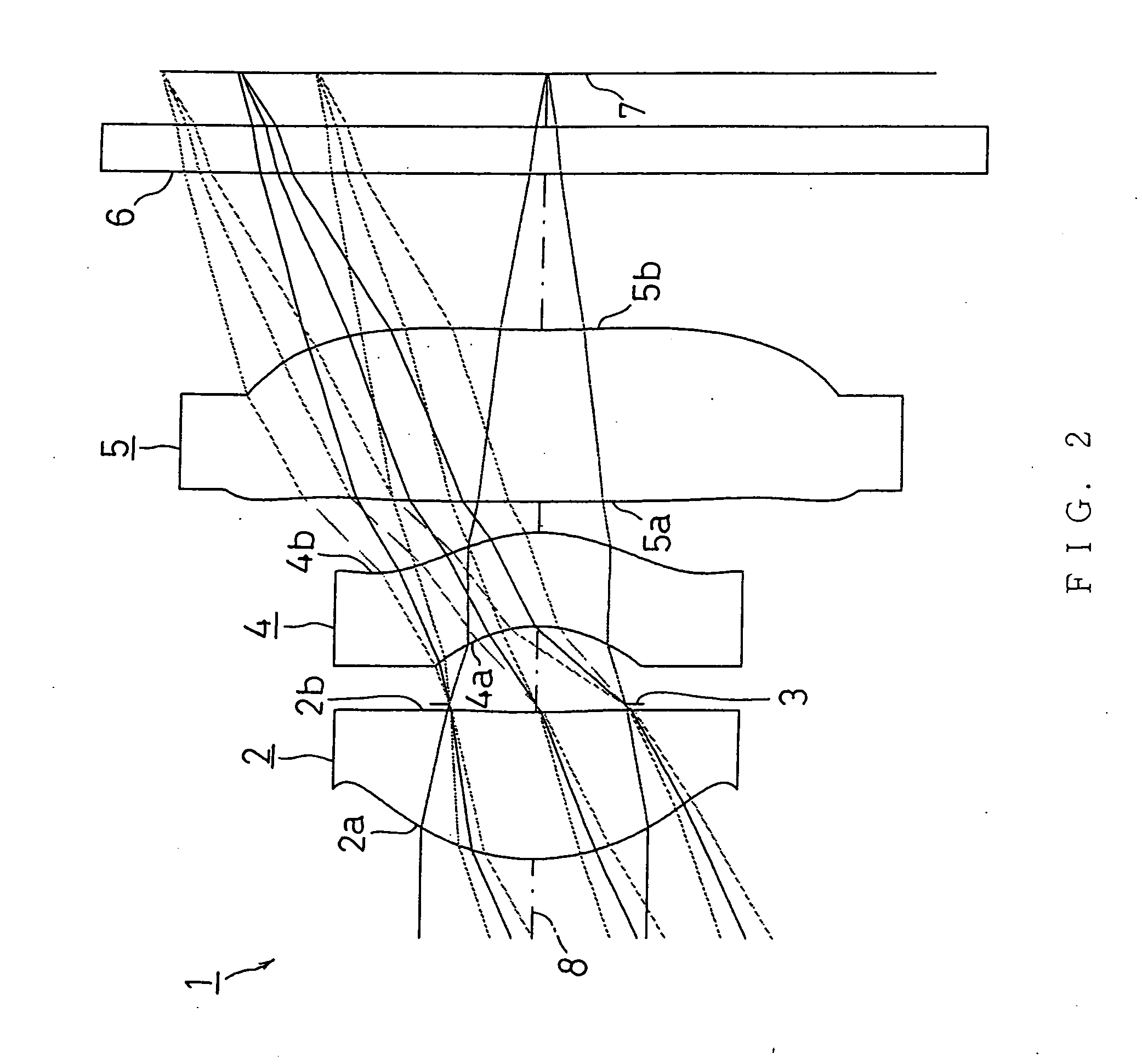
[0113] Next, EXAMPLES of the present invention will be described by referring to FIG. 2 to FIG. 23.
[0114] In the EXAMPLES, F no denotes F number, ω denotes a half view angle, and r denotes a center radius curvature. Further, d denotes a distance to the next optical surface, nd denotes the index of refraction to the d line, and vd denotes the Abbe number (d line-based).
[0115] k, A, B, C, and D denote each coefficient in a following expression (10). Specifically, the shape of the aspherical surface of the lens is expressed by the following expression provided that the direction of the optical axis 8 is taken as the Z axis, the direction orthogonal to the optical axis 8 as the X axis (the height direction), the traveling direction of light is positive, k is the constant of cone, A, B, C, and D are the aspherical coefficients, and r is the center radius curvature.
Z(X)=r−1X2 / [1+{1−(k+1)r−2X2}1 / 2]+AX4+BX6+CX8+DX10 (10)
[0116] In the following EXAMPLES, reference code E used for a numeri...
first example
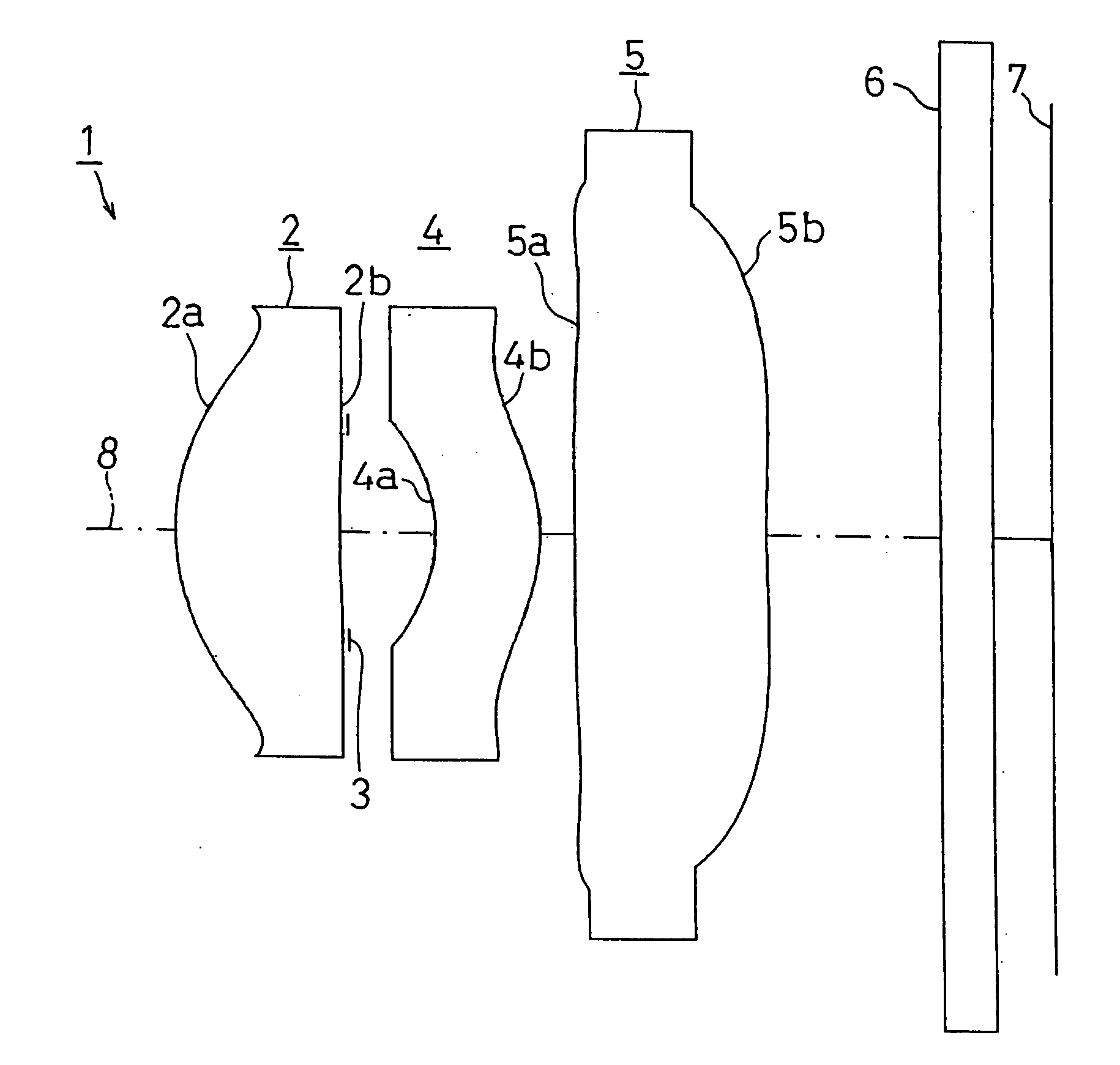
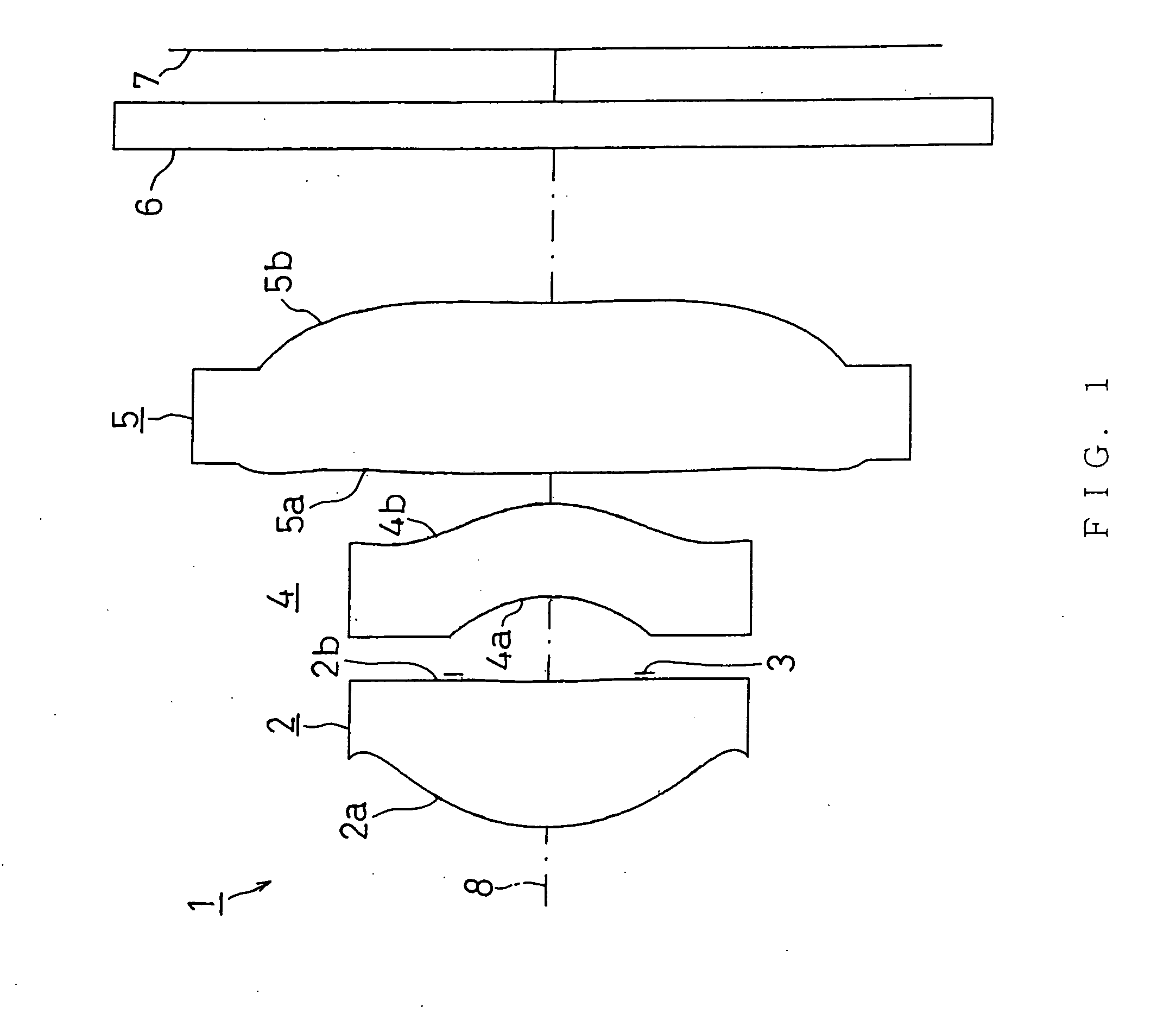
[0117]FIG. 2 shows FIRST EXAMPLE of the present invention. The imaging lens 1 in FIRST EXAMPLE shown in FIG. 2 is the same imaging lens 1 as that shown in FIG. 1.
[0118] The imaging lens 1 of FIRST EXAMPLE was set under the following condition. [0119] (Lens Data)
[0120] f=4.14 mm, F no=2.8
Face Number(Object Point)rdndvd1(First Face of First Lens)1.430.951.531056.02(Second Face of First Lens)8.810.053(Diaphragm)0.000.504(First Face of Second Lens)−0.920.601.585030.05(Second Face of Second Lens)−1.120.206(First Face of Third Lens)−40.981.101.531056.07(Second Face of Third Lens)9.521.008(First Face of Cover Glass)0.000.301.516864.29(Second Face of Cover Glass)0.00(Image Surface)
[0121]
FaceNumberkABCD1−1.03.9E−29.7E−31.8E−2−3.2E−223.0E+1−6.0E−3−2.4E−12.0E−1043.8E−11.8E−12.1E−11.8E−105−4.3E−11.7E−11.1E−1−2.6E−2−3.2E−36−8.4E+13.3E−2−9.9E−3−1.7E−36.1E−471.0E+1−7.4E−21.8E−2−3.0E−32.3E−8
[0122] Under such conditions, L / fl=1.19 was achieved, thereby satisfying the expression (1). f1 / fl=0.739 ...
second example
[0125]FIG. 4 shows SECOND EXAMPLE of the present invention. The imaging lens 1 of SECOND EXAMPLE shown in FIG. 4 was set under the following condition. [0126] (Lens data)
[0127] f=4.12 mm, F no=2.8
Face Number(Object Point)rdndvd1(First Face of First Lens)1.460.951.531056.02(Second Face of First Lens)10.000.053(Diaphragm)0.000.504(First Face of Second Lens)−0.910.621.585030.05(Second Face of Second Lens)−1.110.206(First Face of Third Lens)−50.001.101.531056.07(Second Face of Third Lens)11.111.008(First Face of Cover Glass)0.000.301.516864.29(Second Face of Cover Glass)0.00(Image Surface)
[0128]
FaceNumberkABCD1−1.03.8E−28.3E−31.7E−2−3.2E−223.4E+1−5.6E−3−2.4E−12.0E−1043.3E−11.8E−12.1E−12.1E−105−4.3E−11.7E−11.1E−1−2.5E−2−2.7E−364.3E+23.2E−2−9.8E−3−1.6E−36.1E−471.6E+1−7.3E−21.8E−2−3.0E−31.2E−5
[0129] Under such conditions, L / fl=1.21 was achieved, thereby satisfying the expression (1). f1 / fl=0.750 was achieved, thereby satisfying the expression (2). f1 / f2=0.0512 was achieved, thereby sati...
PUM
 Abstract
Description
Claims
Application Information