Nano-scaled graphene plate-reinforced composite materials and method of producing same

a graphene plate and composite material technology, applied in the field of nanocomposite materials, can solve the problems of high material cost, cnts are known to be extremely expensive, and hinder the widespread application of cnts, and achieve the effect of reducing material cost and reducing material cos

Active Publication Date: 2007-04-26
GLOBAL GRAPHENE GRP INC
View PDF7 Cites 80 Cited by
  • Summary
  • Abstract
  • Description
  • Claims
  • Application Information

AI Technical Summary

Benefits of technology

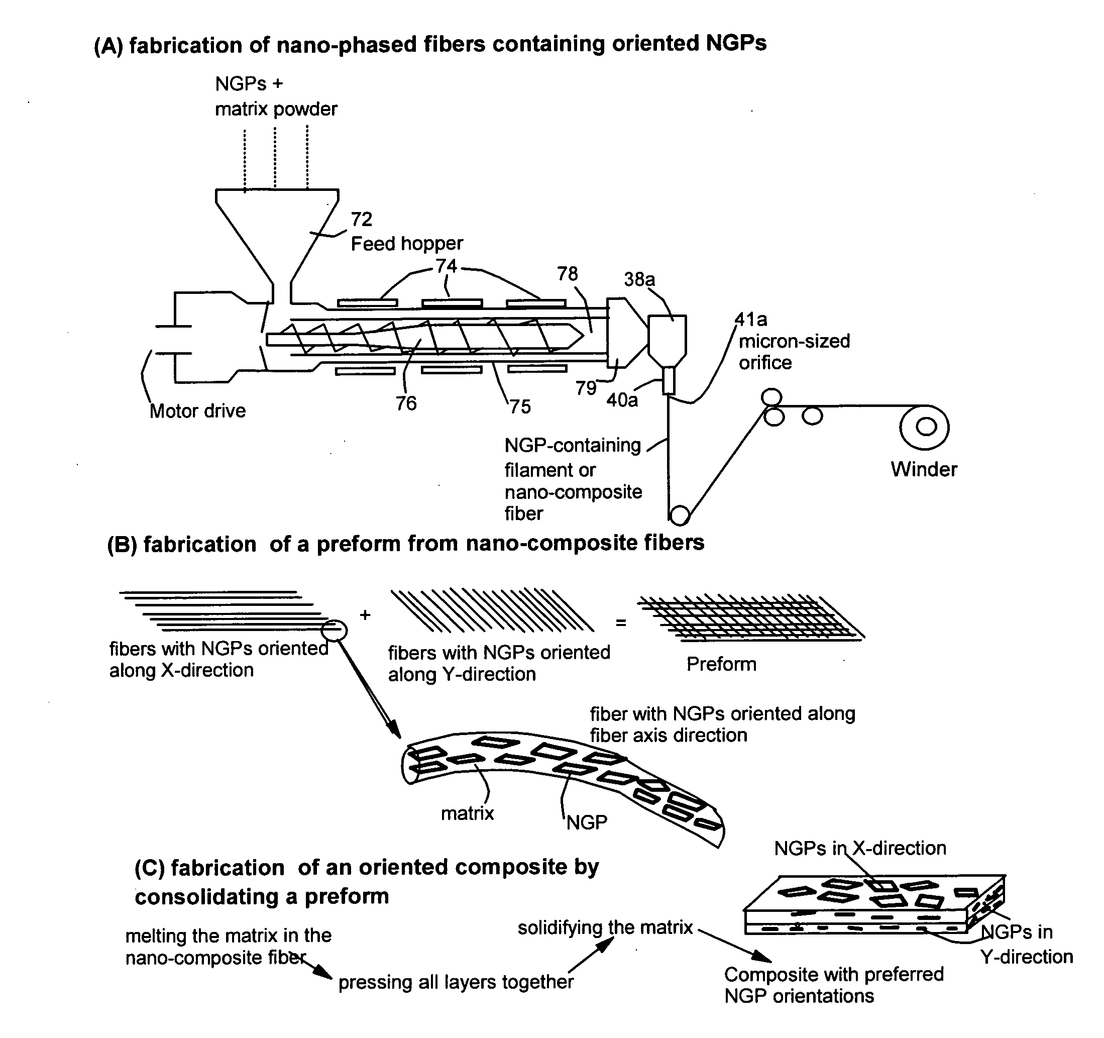
[0010] Briefly described, example embodiments of the present invention provide improved methods of making a composite composition that includes a matrix material and dispersed NGPs as a reinforcement phase. The NGPs preferably are substantially aligned along at least one specified axis or direction. The method preferably includes: (a) providing a mixture of NGPs and a matrix material in a fluent state, (b) extruding the mixture through a small orifice under a high shear force to form a long or continuous-length filament, (c) aligning a selected number of the filament segments along at least one preferred direction to form a NGP-matrix preform, wherein the filament segments are substantially parallel to each other and to the at least one preferred direction, and (d) consolidating the preform to produce the composite composition.

Problems solved by technology

However, there are several drawbacks associated with carbon nanotube-reinforced composites.
First, CNTs are known to be extremely expensive due to the low yield and low production and purification rates commonly associated with all of the current CNT preparation processes.
The high material costs have significantly hindered the widespread application of CNTs.
However, CNTs tend to form a tangled mess resembling a hairball, which is difficult to work with.
This and other difficulties have limited efforts toward realizing a composite material containing well-dispersed CNTs with preferred orientations.

Method used


Image

  • Nano-scaled graphene plate-reinforced composite materials and method of producing same
  • Nano-scaled graphene plate-reinforced composite materials and method of producing same
  • Nano-scaled graphene plate-reinforced composite materials and method of producing same

Examples


Embodiment Construction

[0018] The present invention may be understood more readily by reference to the following detailed description of the invention taken in connection with the accompanying drawing figures, which form a part of this disclosure. It is to be understood that this invention is not limited to the specific devices, methods, conditions or parameters described and / or shown herein, and that the terminology used herein is for the purpose of describing particular embodiments by way of example only and is not intended to be limiting of the claimed invention. Also, as used in the specification including the appended claims, the singular forms “a,”“an,” and “the” include the plural, and reference to a particular numerical value includes at least that particular value, unless the context clearly dictates otherwise. Ranges may be expressed herein as from “about” or “approximately” one particular value and / or to “about” or “approximately” another particular value. When such a range is expressed, anothe...


PUM

PropertyMeasurementUnit
diameteraaaaaaaaaa
angleaaaaaaaaaa
diameteraaaaaaaaaa

Abstract

Disclosed are a nano-composite composition and a method of making such a composite that is composed of a matrix material and dispersed reinforcement nano-scaled graphene plates (NGPs) that are substantially aligned along at least one specified direction or axis. The method comprises: (a) providing a mixture of nano-scaled graphene plates (NGPs) and a matrix material in a fluent state; (b) extruding the mixture to form a filament wherein NGPs are aligned along a filament axis; (c) aligning a plurality of segments of the filament in a first direction, or moving the filament back and forth along a first direction and its opposite direction, to form a NGP-matrix filament preform; and (d) consolidating the preform to form the nanocomposite material. Also disclosed is a method of making a nano-composite fiber.

Description

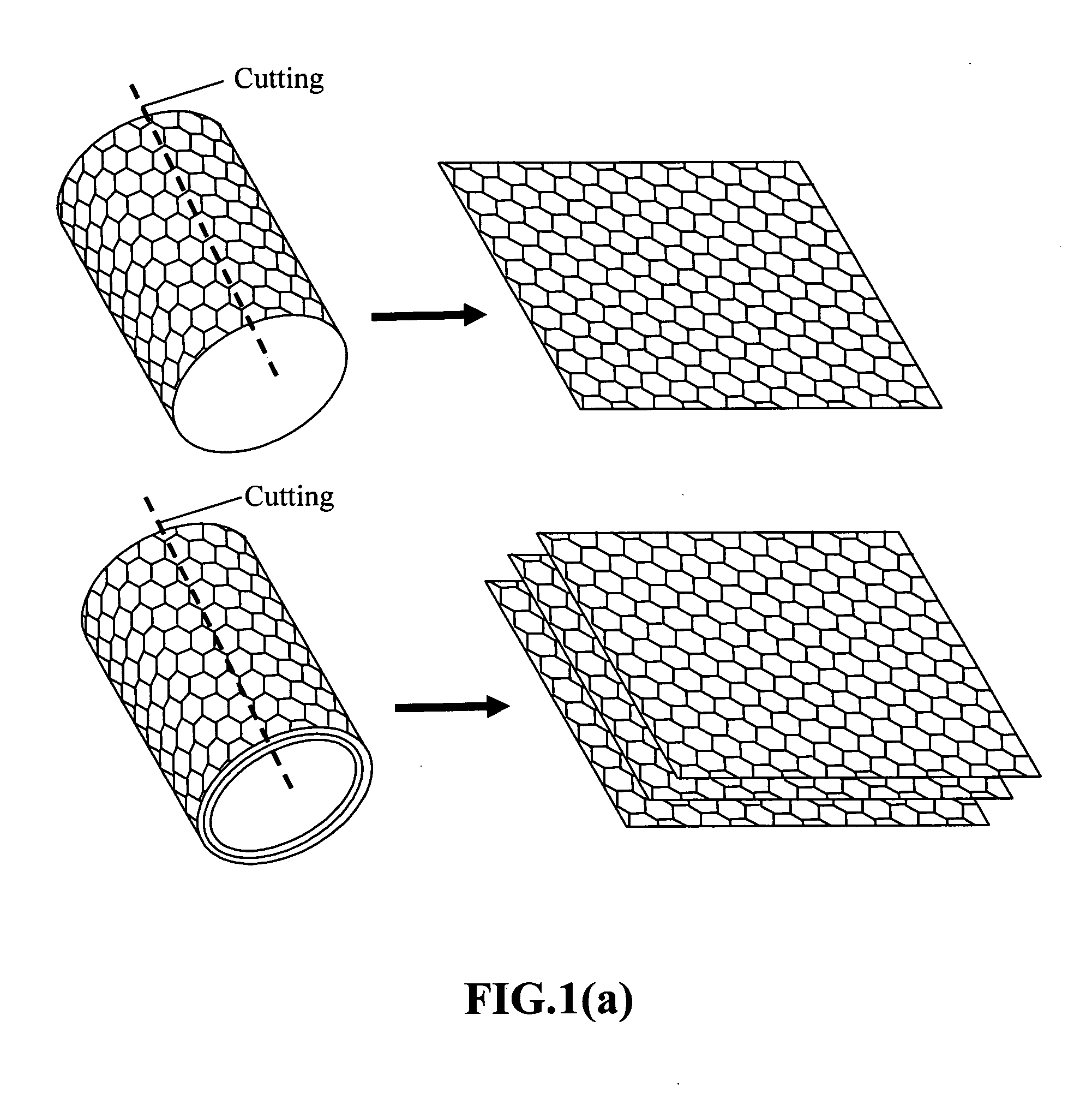
[0001] This invention is based on the results of a research project sponsored by the US DoE SBIR Program. The US government has certain rights on this invention.FIELD OF THE INVENTION [0002] The present invention relates generally to the field of nano-composite materials, and more particularly to nano-graphene plate-reinforced composite materials (NGP composites) and methods for the production of NGP composites. In particular examples of the invention, the nanometer-sized graphene plates of the material exhibit a controlled degree of preferred orientation. BACKGROUND OF THE INVENTION [0003] Carbon nanotubes (CNT) are nanometer-scale sized tube-shaped molecules having the structure of a graphite molecule rolled into a rube. A nanotube can be single-walled or multi-walled, dependent upon conditions of preparation. Carbon nanotubes typically are electrically conductive and mechanically strong and stiff along their length. Nanotubes typically also have a relatively high aspect ratio (le...

Claims


Application Information

Patent Timeline
Patent Type & Authority Applications(United States)
IPC IPC(8): B32B5/16B29C47/00
CPCB29B11/10Y10S977/778B29C70/202B29K2105/0827B29K2105/0836B29K2105/0845B29K2105/162B29L2031/731B82Y30/00C08J5/005C08J5/048D01F1/10Y10T428/24124Y10T428/25B29B11/16Y10T428/249945Y10T428/249927Y10T428/249929Y10T428/249924
Inventor GUO, JIUSHENGSONG, LULUZHAMU, ARUNAJANG, BOR Z.
Owner GLOBAL GRAPHENE GRP INC
Why Eureka
Try Eureka