Modular industrial equipment facility

a technology for industrial equipment and modular buildings, applied in industrial buildings, special buildings, parkings, etc., can solve the problems of inability to meet the needs of certain applications, inability to meet the needs of industrial equipment, and inability to include adequate backup systems or system redundancies,

Inactive Publication Date: 2007-05-03
OHIO TRANSMISSION CORP
View PDF17 Cites 40 Cited by
  • Summary
  • Abstract
  • Description
  • Claims
  • Application Information

AI Technical Summary

Benefits of technology

[0004] Deficiencies in and of the prior art are overcome by the present invention, the exemplary embodiment of which provides a modular facility suitable for housing a variety of industrial equipment or devices such as, for example, high-output air compressor/dryers. In accordance with one aspect of the present invention, an industrial system is provided. This system includes a plant for performing one or more industrial processes and a modular industrial equipment facility connected to the plant. The modular equipment facility further includes a plura

Problems solved by technology

However, many modular buildings or structures, although often highly functional, are unacceptable for certain applications because they include multiple modules or units that are connected to one another in a manner that creates a structure or structures that appear to be incomplete, i.e., unfinished, or non-permanent.
Facilities of this nature are often undesirable because they are deemed unacceptable by labor unions or because they negatively impact the appearance of the physical environment in which they are located.
However, many industrial equipment facilities, including those that are modular in nature, do not include ade

Method used


Image

  • Modular industrial equipment facility
  • Modular industrial equipment facility
  • Modular industrial equipment facility

Examples


Embodiment Construction

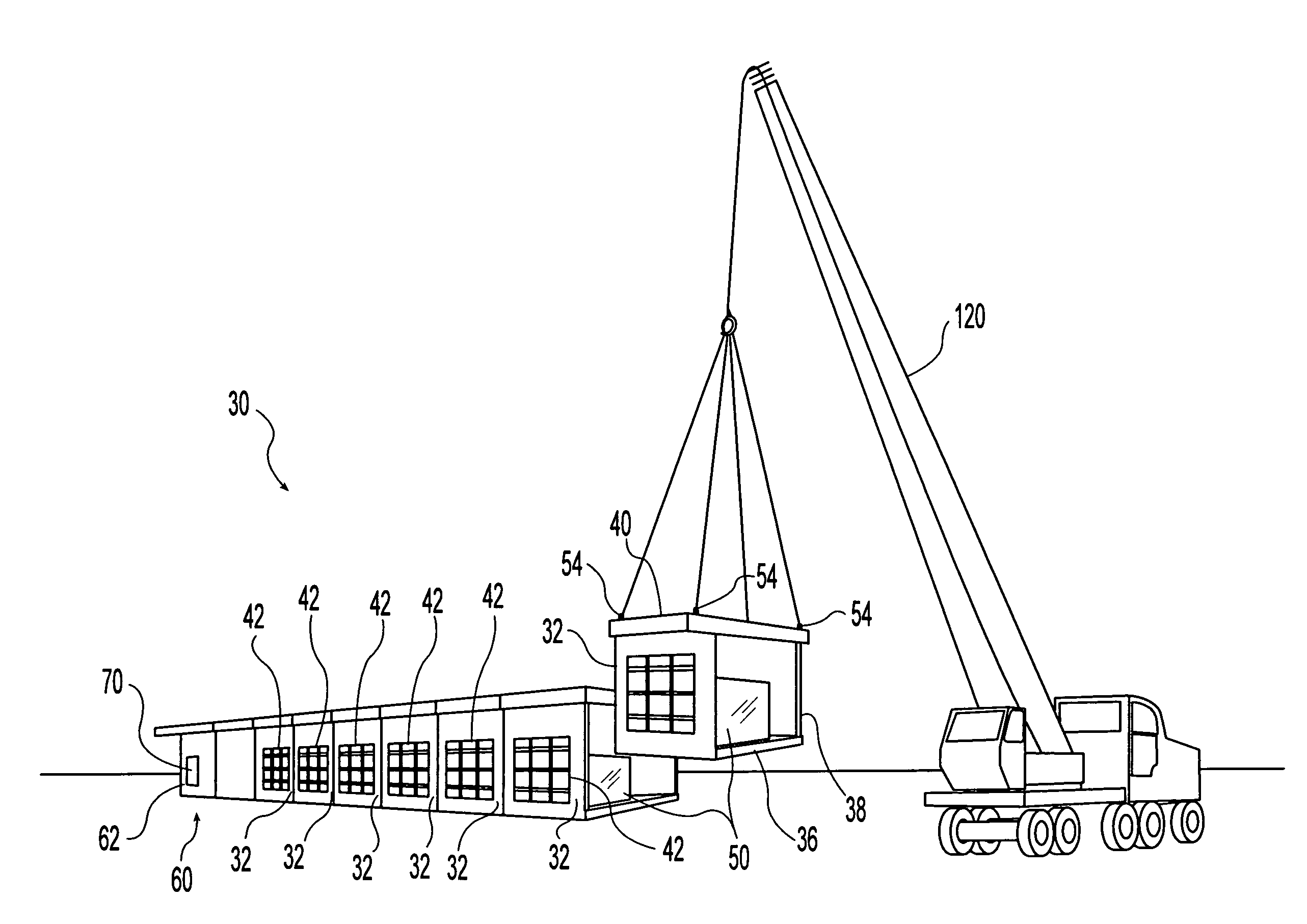
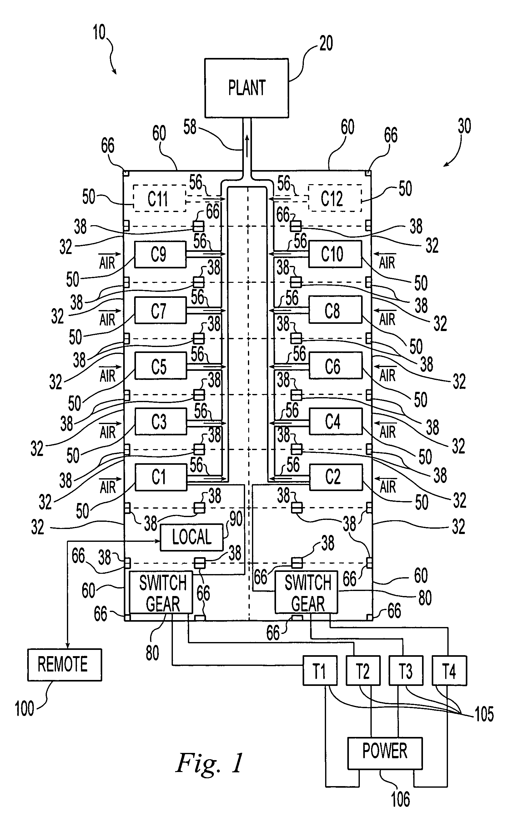
[0017] This invention relates to a reconfigurable modular industrial equipment facility for use with a factory, manufacturing plant or other industrial system or operation. An exemplary embodiment of this facility includes a plurality of pre-fabricated, portable equipment modules that are typically transported to and arranged at a predetermined location. These equipment modules further include: a plurality of internal equipment modules (i.e., for placement on the interior or middle portion of the structure), wherein each internal module is configured to operate independently of or in combination with the other internal modules in the event of a partial system failure; and a plurality of terminal modules (i.e., for placement on the end portions of the structure) for use in combination with the plurality of internal modules. When final construction / assembly of the facility of the present invention is complete, the internal modules and terminal modules form a single, integrated structu...


PUM


Abstract

A modular industrial equipment facility is provided. This facility includes a plurality of pre-assembled, portable modules that may further include a plurality of internal modules, and a plurality of terminal modules for connecting to the plurality of internal modules, wherein each module may be configured to operate either in combination with or independent of the other modules. These modules are typically intended for use with heavy, industrial grade equipment. The internal modules and terminal modules may be arranged to form a single, integrated structure that has the appearance of a permanent, non-modular building. This invention may also include a computerized monitoring and control system that may further include a local component that monitors and controls the operation of equipment that may be housed in the various modules; and a remote monitoring and control component that is capable of monitoring and controlling the operation of the equipment in the various modules. Pre-installed ductwork and computerized air handling allow the facility to be expanded or contracted without significant structural modifications.

Description

BACKGROUND OF THE INVENTION [0001] This invention relates in general to a facility for use with industrial equipment, and in particular to a modular equipment facility for use with heavy industrial equipment such as, for example, air compressor / dryer units. [0002] In certain circumstances, the use of prefabricated, modular buildings for purposes such as constructing electrical facilities and residential housing may be an acceptable alternative to more traditional on-site construction methods. The use of individual building modules or units may save time and may reduce the overall complexity associated with some construction projects. However, many modular buildings or structures, although often highly functional, are unacceptable for certain applications because they include multiple modules or units that are connected to one another in a manner that creates a structure or structures that appear to be incomplete, i.e., unfinished, or non-permanent. For example, many modular faciliti...

Claims


Application Information

Patent Timeline
IPC IPC(8): E04H1/00
CPCE04H5/02
Inventor SCHOENY, STEVENELSON, GARY
Owner OHIO TRANSMISSION CORP
Why Eureka
Try Eureka