
Thermal control system and method

a technology of temperature control and system, applied in the direction of fluid circulation arrangement, refrigeration machines, lighting and heating apparatus, etc., can solve the problems of unstable loop gain of servo system, time delay in cooling load, etc., to reduce the amount of cooling available, shorten response time, and improve the effect of temperature control

Inactive Publication Date: 2007-05-03
ADVANCED THERMAL SCI
View PDF6 Cites 51 Cited by
  • Summary
  • Abstract
  • Description
  • Claims
  • Application Information

AI Technical Summary

Benefits of technology

"The invention is a thermal control system for a saturated fluid that improves efficiency and stability across a range of load temperatures. The system uses a vapor separator to extract vapor components in the condensed fluid after expansion before mixing with compressed gas, which improves cooling efficiency at very low temperatures. The system also includes a counter-current heat exchanger to interchange thermal energy between the incoming input and the out-going refrigerant, which increases the temperature level of the input to the load and reduces the temperature of the return fluid. The system also includes a computer controlled solenoid bypass to remove some of the flow from the hot gas line when full hot gas flow might tend to make the loop gain of the servo system unstable and / or reduce the amount of cooling available at temperatures within the desired range. The control circuit adaptations can introduce temporary and short term commands to shorten response times and increase yield rates."

Problems solved by technology

This bypass is operated to remove some of the flow from the hot gas line when full hot gas flow might tend to make the loop gain of the servo system unstable and / or reduce the amount of cooling available at temperatures within the desired range.
The result introduces a time delay in cooling the load to enable closer control of temperature.

Method used


Image

  • Thermal control system and method
  • Thermal control system and method
  • Thermal control system and method

Examples


Embodiment Construction

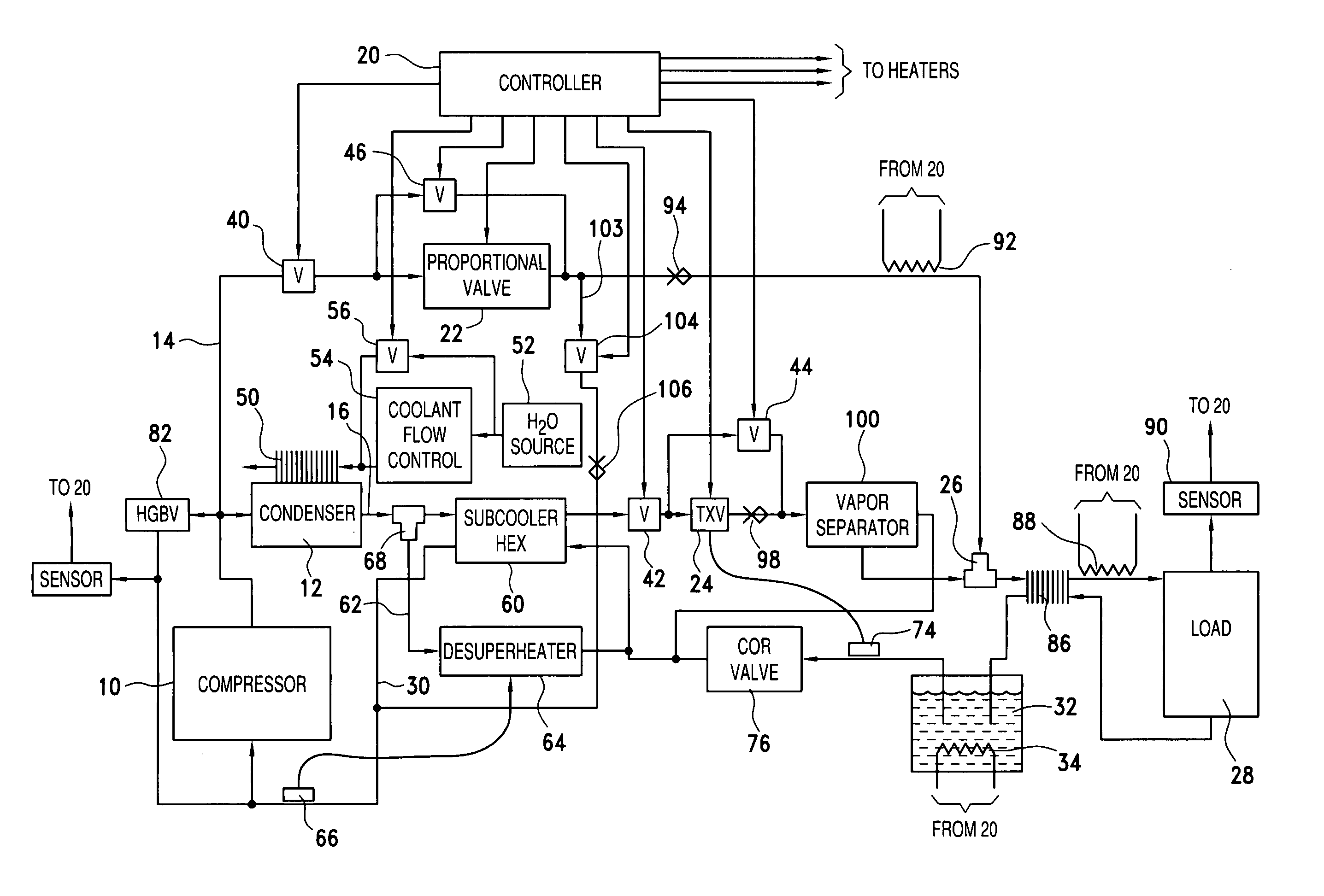
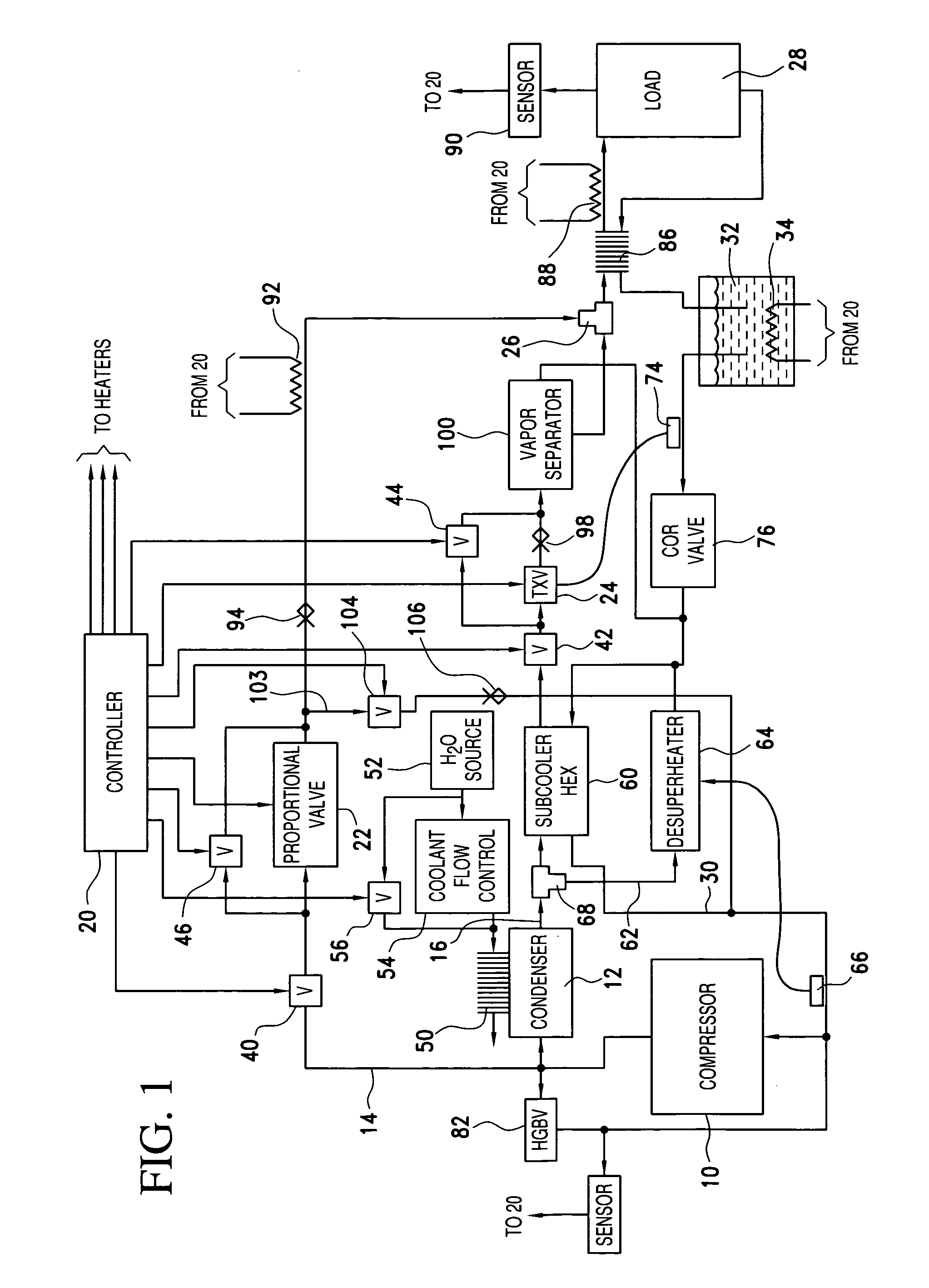
[0014] Referring now specifically to FIG. 1, a temperature control system is shown utilizing a novel refrigeration / heating cycle in accordance with the above-referenced previously filed Cowans et al application Ser. No. 11 / 057,383. The present system integrally incorporates features in this context for achieving improved stability and / or efficiency when directly transferring thermal energy using saturated fluids.

[0015] In FIG. 1, a compressor 10, which may use a conventional refrigerant such as R507, or a different refrigerant depending upon the application, feeds compressed hot gas into a condenser 12 which also is arranged as part of a pressure regulating system. The compressor 10 output is fed into a hot gas line 14 which is separately split to a condensed refrigerant line 16, the flow proportions being controlled by a digital controller system 20, as described in the previously filed application. The hot gas line 14 includes a proportional valve 22 operated by the controller 20...


PUM


Abstract

Improvements in systems and methods which employ a two-phase fluid, such as a refrigerant, as a saturable fluid in direct heat transfer relation to a thermal load, are realized by extraction of vapor from the saturated fluid before heat exchange. Moreover, automatic changing of the paths under command of a controller enables charges to be effected between different modes at higher rates than in other systems by employing the variety of modes available in the direct transfer system.

Description

REFERENCE TO PRIOR APPLICATIONS [0001] This invention relies for priority on previously filed application Ser. No. 11 / 057,383 of Kenneth W. Cowans et al, filed Feb. 15, 2005 and entitled “Thermal Control System and Method”, and on provisional application 60 / 733,078 filed Nov. 4, 2005 by Kenneth W. Cowans et al and entitled “Thermal Control System and Method”.BACKGROUND OF THE INVENTION [0002] The above mentioned utility application of Cowans et al discloses a system and method of temperature control in which the temperature of a load is varied by thermal exchange with a saturated fluid directly, without requiring an intervening heat transfer fluid. Typically the saturated fluid is a refrigerant used in pure gas phase, or pure liquid phase, or more often in a mixed or saturated phase. In accordance with the invention, the vaporizable refrigerant is processed through substantially conventional compression and condensation steps as provided by commercially available equipment. However,...

Claims


Application Information

Patent Timeline
Patent Type & Authority Applications(United States)
IPC IPC(8): F25B43/00F25B41/00
CPCF25B40/00F25B41/00F25B2400/01F25B2400/0403F25B2400/0411
Inventor COWANS, KENNETH W.COWANS, WILLIAM W.ZUBILLAGA, GLENN W.
Owner ADVANCED THERMAL SCI
Learn More