
On-line adjustable coal flow distributing device

a distribution device and adjustable technology, applied in lighting and heating equipment, combustion process, lump/pulverized fuel feeder/distribution, etc., can solve the problems of increasing the pressure drop of the coal pipe, difficult to achieve uniform coal flow distribution to the coal pipes, and increasing the difficulty of coal flow distribution to the burners. achieve the effect of reducing the pressure drop of the system, reducing the difficulty of coal flow distribution, and efficient controlling the balance of multiple coal flows

Inactive Publication Date: 2007-05-03
FOSTER WHEELER ENERGY CORP
View PDF6 Cites 18 Cited by
  • Summary
  • Abstract
  • Description
  • Claims
  • Application Information

AI Technical Summary

Benefits of technology

[0010] An object of the present invention is to provide a riffle configuration in a simple and reliable method of and apparatus for efficiently controlling the balance of multiple coal flows in a pulverized coal fired boiler system, without significantly increasing the pressure drop of the system.
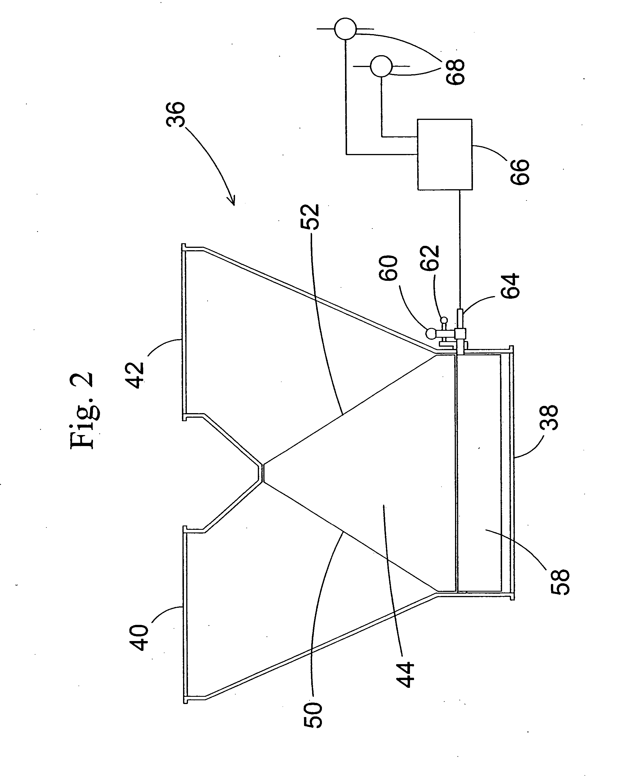
[0014] By adjusting one or more of the individual vanes disposed upstream of the partition walls from an inline position to a position at least partially blocking the inlet to one or more flow channels, the flow of coal and air through the channels can be reduced. As an object of the present invention, while coal is transported in the coal pipes as concentrated ropes, which typically hit a few of the flow channels only, a considerable portion of the coal may be redistributed to flow to the neighboring channels by partially or fully blocking the inlets to one or at most a few of-the channels. By adjusting the vanes properly, the coal flow can be distributed evenly to the outlet pipes. In some cases, there is also a need to specifically bias the coal distribution, for example, to address emissions or slagging problems. By adjusting the vanes properly, it is also possible to obtain such a biased coal distribution.
[0015] The pivotable vanes in accordance with the present invention allow balancing of the outlet coal flows without having to use flow channels in the riffle that are so narrow that a significant pressure drop in the riffle is created. In most cases, the device in accordance with the present invention renders it possible to balance the coal flow distribution by turning one or at most a few vanes in the riffle. Thus, most of the vanes can be maintained inline with the flow, a pressure drop does not severely increase, and the velocity or distribution of primary air, which is spread to all of the channels, is not significantly affected.
[0017] The coal pipe junction preferably comprises two or more outlet openings, one to each of the corresponding downstream coal pipes. When the junction has only two outlet openings, the riffle enclosure advantageously comprises parallel flow channels leading alternately to each of the outlet openings. By disposing a pivotable vane upstream of every second of the partition walls between the flow channels and a fixed partition wall extension between the pivotable vanes, it is possible to close or to reduce the flow to any one of the channels, and thereby to balance the coal flows by redistributing a portion of an unfavorable high coal flow from a channel to its neighboring channel.
[0018] When the riffle comprises N outlet openings, where N is larger than two, a fixed partition wall extension is preferably disposed upstream of every Nth partition wall and an individually pivotable vane is preferably disposed upstream of all other partition walls. By pivoting N-I adjacent vanes, it is then usually possible to balance the coal flow to the N outlet openings. To provide the highest controlling flexibility, it is also possible to dispose an adjustable vane upstream of each of the partition walls, although such a riffle is somewhat more complicated than the ones with fixed wall extensions between the vanes.

Problems solved by technology

However, achieving a uniform coal flow distribution to the coal pipes is often a difficult task.
When reaching a coal pipe junction, the rope may be directed mainly to one downstream coal pipe, and the distribution of coal to the burners may therefore become highly unbalanced.
However, such a swirler increases the pressure drop in the coal pipe.
Also, in cases in which an unbalanced distribution of coal is observed, such a swirler cannot be adjusted to correct the flows.
However, channels that are too narrow cause a high flow resistance.
However, in this configuration, a too large imbalance may be caused.
Such a device is, however, quite a complicated construction and prone to wearing.

Method used


Image

  • On-line adjustable coal flow distributing device
  • On-line adjustable coal flow distributing device
  • On-line adjustable coal flow distributing device

Examples


Embodiment Construction

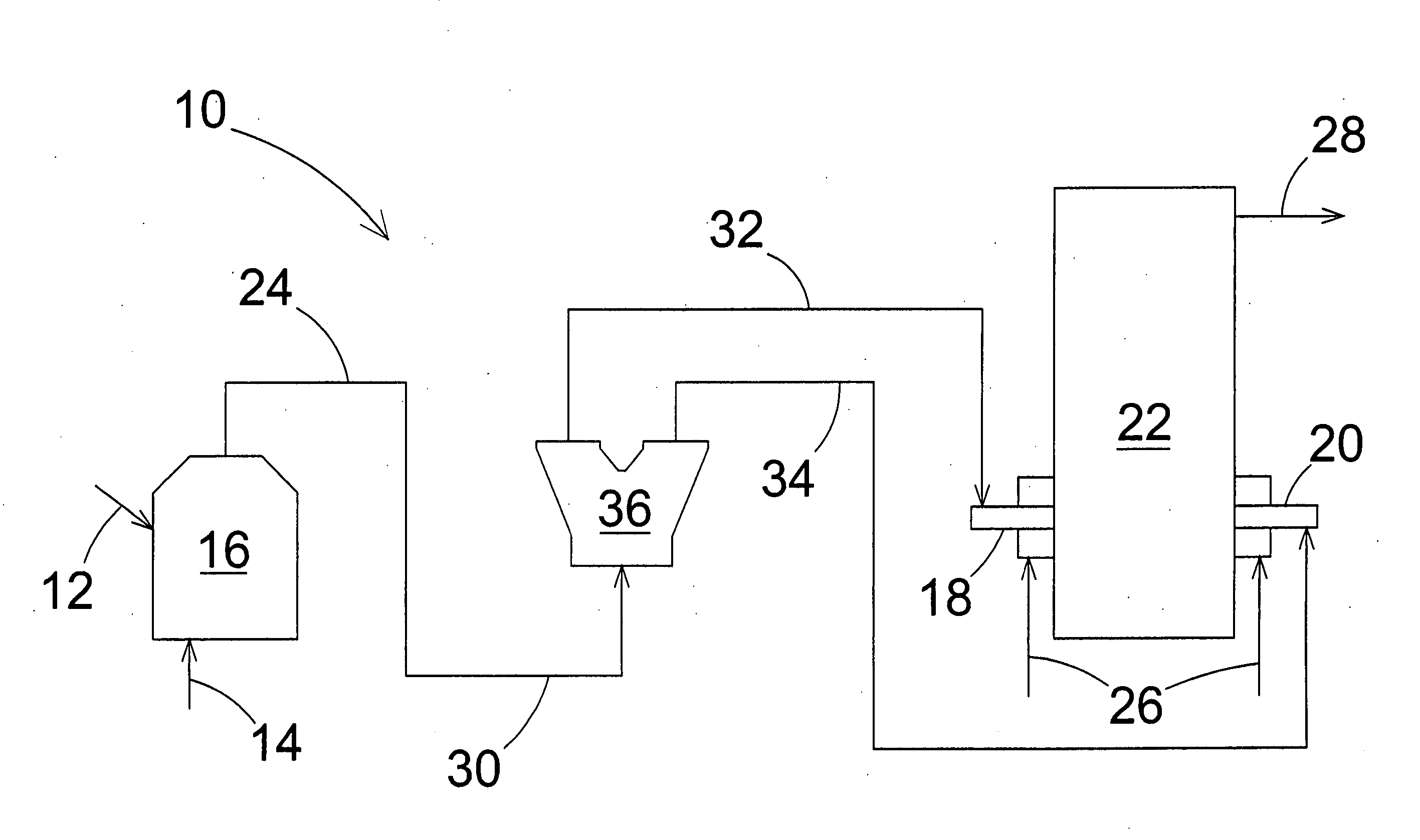
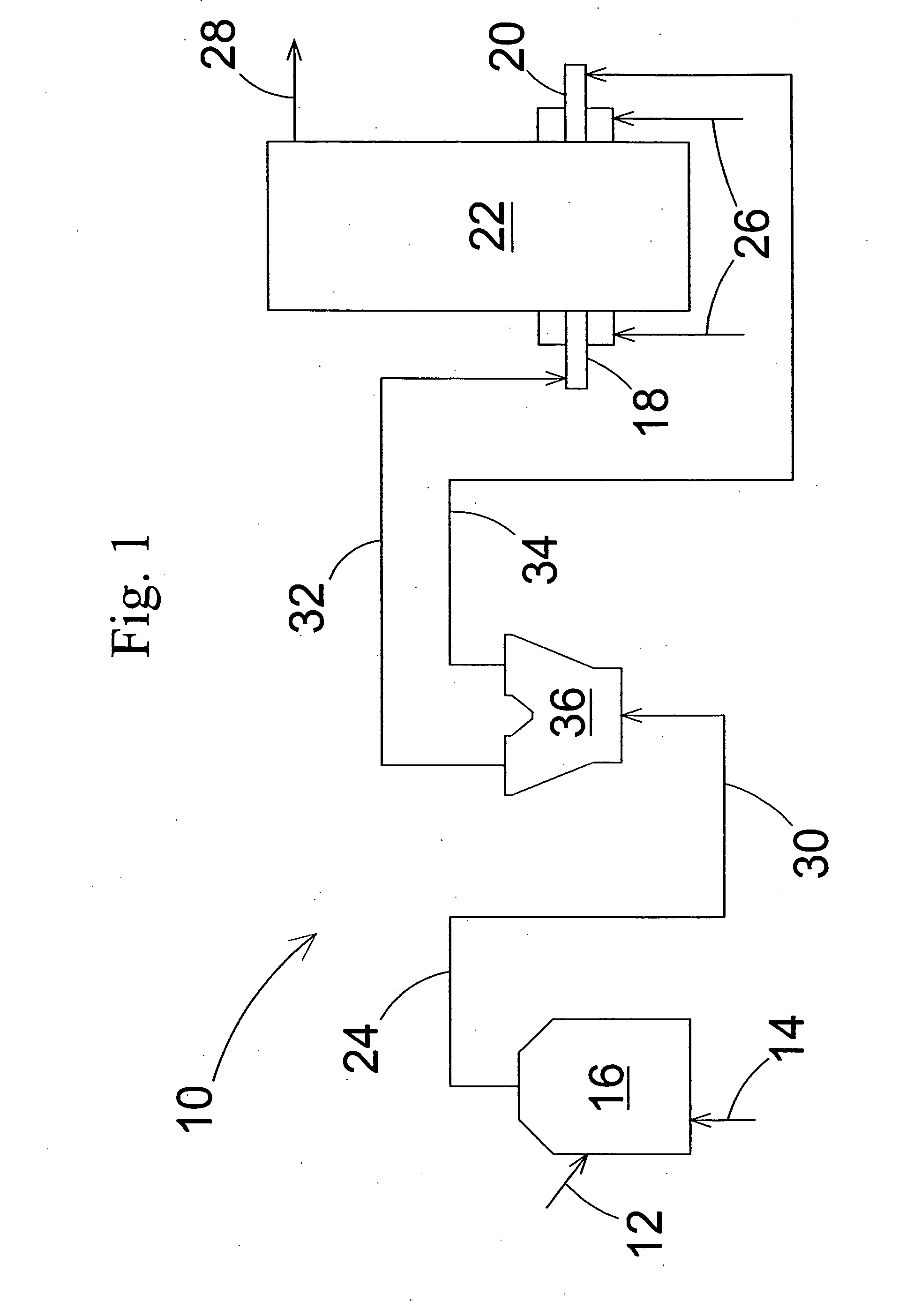
[0025] Referring now in greater detail to the drawings, FIG. 1 schematically shows an overall view of a pulverized coal-fired boiler system 10. Coal 12 and air 14 are introduced into a pulverizer 16 in which the coal is pulverized into a size suitable for combustion in each of two burners 18, 20 disposed on the sidewalls of a boiler 22. In other types of boilers, the burners 18, 20 can be disposed on the corners, roof, and / or arches of the boiler. Pulverized coal and primary air are conveyed along a coal feed system 24 from the pulverizer 16 to the burners 18, 20, where the coal is combusted by primary air and secondary air 26. Exhaust gases produced in the combustion process are discharged from the boiler through a discharge gas channel 28.

[0026] The coal feed system 24 comprises, in the simple pulverized coal firing boiler system shown in FIG. 1, an upstream pipe 30, connected to the pulverizer 16, and two downstream pipes 32 and 34, connected to the burners 16 and 18, respective...


PUM


Abstract

A method of and an apparatus for operating a pulverized coal-fired boiler system, which includes at least one coal pulverizer in flow connection with at least two burners disposed on a boiler enclosure by a coal feed system having a coal pipe junction with a riffle enclosure including a plurality of parallel partition walls forming multiple flow channels from an upstream coal pipe to each of at least two downstream coal pipes and a plurality of individually pivotable vanes upstream of the plurality of partition walls, and controlling the distribution of coal between the downstream pipes by pivoting at least one of the vanes. Preferably a coal flow rate is monitored in the downstream coal pipes and at least one of the vanes is pivoted in response to a measured distribution of the coal flow rate.

Description

BACKGROUND OF THE INVENTION [0001] 1. Field of the Invention [0002] The present invention relates to a method of and an apparatus for operating a pulverized coal-fired boiler system including an on-line adjustable coal flow distributing device. The invention particularly relates to controlling the balance of flows of pulverized coal from a coal pipe to multiple coal pipes by using an adjustable riffle in a coal pipe junction. A riffle is an enclosure including a series of parallel flowchannels with rectangular cross sections, leading coal from an inlet pipe alternatively to each of a plurality of outlet pipes. [0003] 2. Description of the Related Art [0004] In a pulverized coal-fired boiler, particulate coal and primary air flow from one or more pulverizers to multiple coal burners disposed on the boiler enclosure, i.e., on the walls, corners, roof and / or arches, of the boiler. Coal is fed to the burners through a coal feed system comprising multiple coal pipes extending from the pu...

Claims


Application Information

Patent Timeline
Patent Type & Authority Applications(United States)
IPC IPC(8): F23K1/00F23B90/00F23K3/02
CPCF23K3/02F23K2203/006F23K2203/105
Inventor JOHN, GRUSHA
Owner FOSTER WHEELER ENERGY CORP
Learn More