Thermoelectric transducer

a transducer and thermoelectric technology, applied in the field of thermoelectric transducers, can solve the problems of micro cracks produced in the thermoelectric element itself, abnormal heat generation, and the thermoelectric element may be broken and completely out of conduction, so as to improve the accuracy of voltages and reduce voltages between the respective terminals

Inactive Publication Date: 2007-05-03
DENSO CORP
View PDF7 Cites 67 Cited by
  • Summary
  • Abstract
  • Description
  • Claims
  • Application Information

AI Technical Summary

Benefits of technology

[0011] Moreover, resistance values between the respective terminals are widely varied by variations in the characteristic of the thermoelectric element itself, distribution of wind speed, and distribution of temperatur...

Problems solved by technology

This failure is caused by micro cracks produced in the thermoelectric element itself by the thermal stress of expansion or contraction developed when the thermoelectric element itself generates heat or is cooled.
When the micro cracks grow, the thermoelectric element may be broken and brought completely out of conduction or may generate heat abnormally by contact resistance before it is completely broken.
When the thermoelectric element generates heat abnormally, there is presented a problem that the electrode member and ...

Method used


Image

  • Thermoelectric transducer
  • Thermoelectric transducer
  • Thermoelectric transducer

Examples


first embodiment

[0032] Hereinafter, a thermoelectric transducer according to the first embodiment of the present invention will be described on the basis of FIG. 1 to FIG. 7.

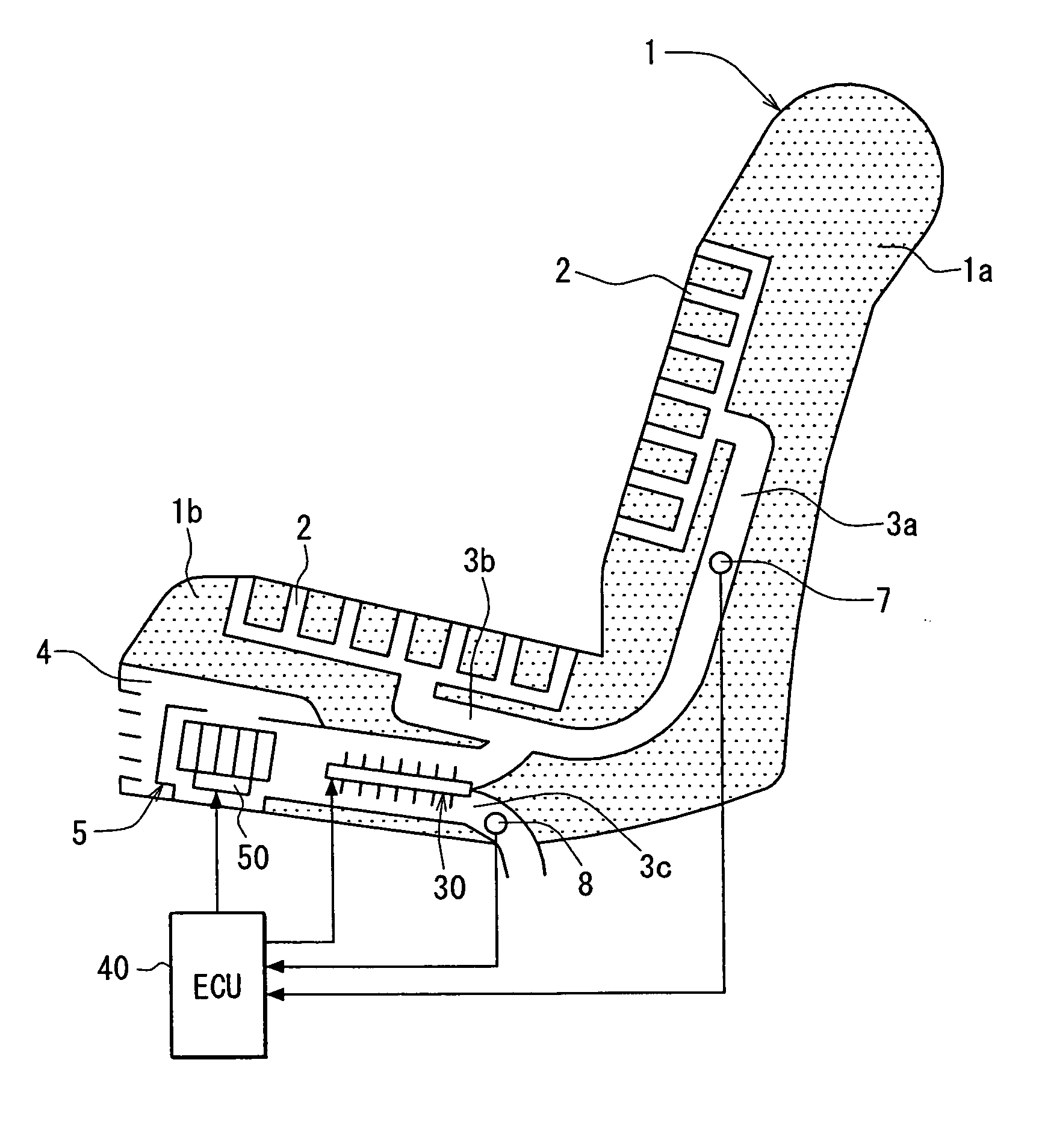
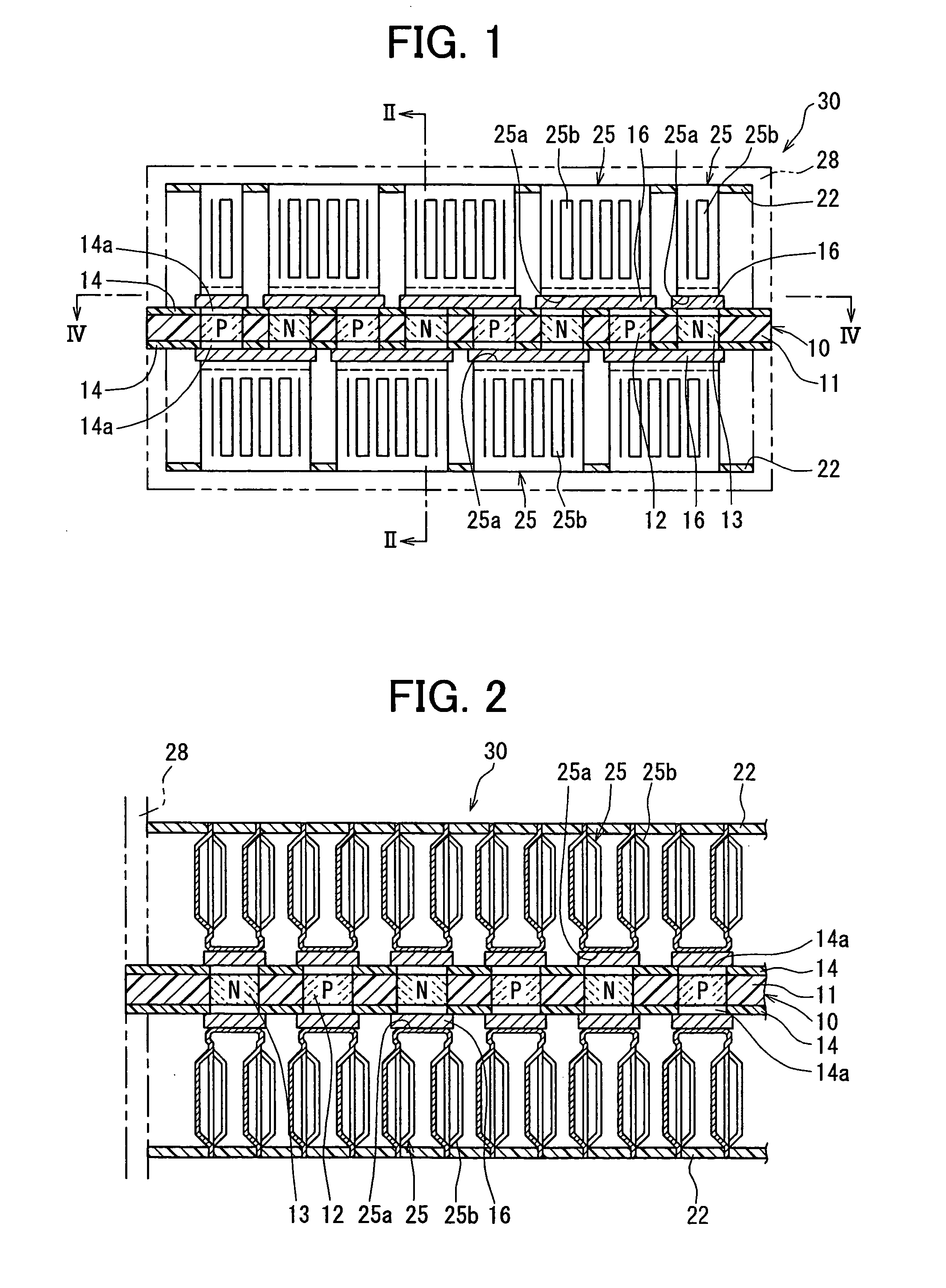
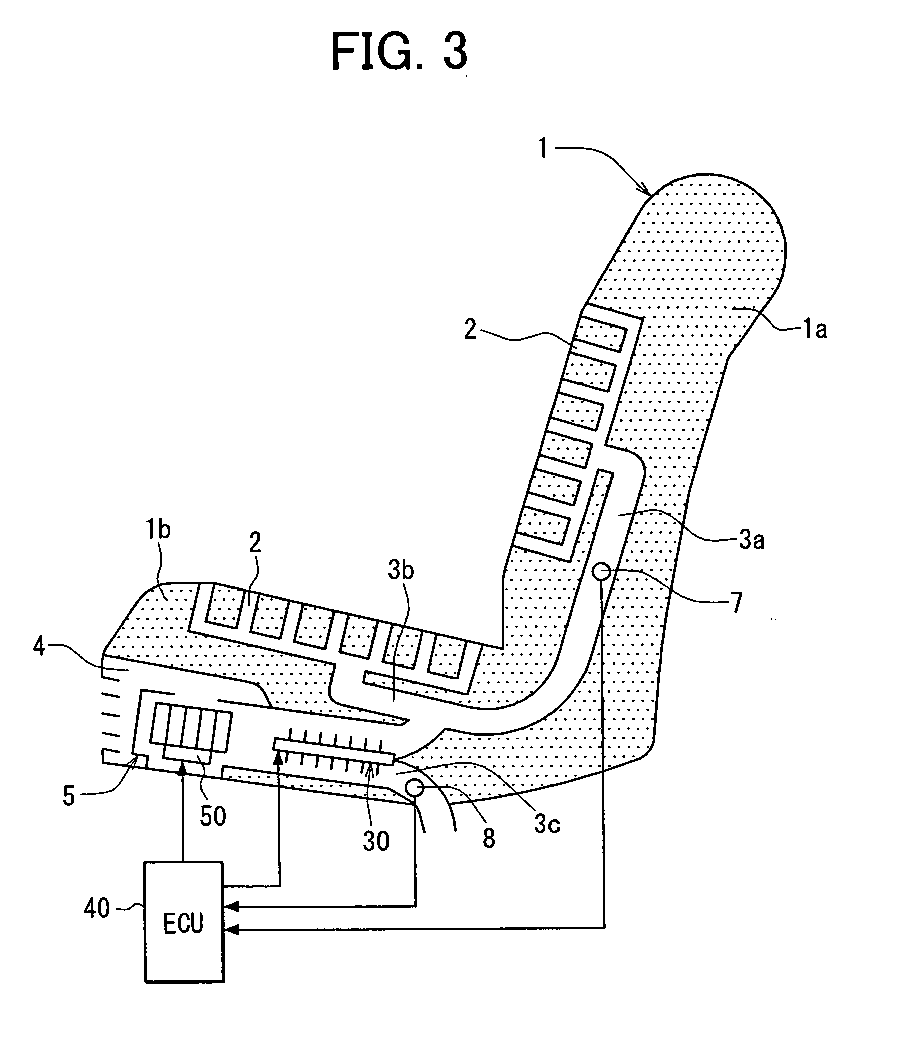
[0033]FIG. 1 is a schematic diagram showing a general construction of a thermoelectric element module 30, and FIG. 2 is a cross-sectional view taken on the line II-II shown in FIG. 1. In this embodiment, the thermoelectric transducer is typically used for a cooling device or / and a heating device mounted on a vehicle. For example, as shown in FIG. 3, the thermoelectric transducer is used for a seat air-conditioning device in which the thermoelectric element module 30 is arranged in a seating portion 1b of a vehicle seat 1 and in which cold air cooled by the thermoelectric element module 30 is blown off from the surface of the seat 1.

[0034] This seat air-conditioning device has the seat 1 having a backing portion 1a and the seating portion 1b, a heating / cooling device 5 arranged in a space 4 formed under the seat 1, and a contr...

second embodiment

[0098] In the above-described first embodiment, the middle terminal 24c is arranged approximately at the middle position between the electric power input terminal 24a and the electric power output terminal 24b. However, the position of the middle terminal 24c is not limited to this, but three middle terminals 24c may be arranged at suitable positions to divide the distance between the electric power input terminal 24a and the electric power output terminal 24b into quarters.

[0099] In this case, if the thermoelectric elements 12, 13 operate normally, the predetermined voltage V0=V1+V2+V3+V4 and voltage V1≅voltage V2 voltage V3≅voltage V4. According to this, the resistance values between the respective terminals 24a, 24b, and 24c are widely varied by variations in the characteristics of the element itself, distribution of wind speed, and distribution of temperature. However, the variations in the voltages between the respective terminals 24a, 24b, and 24c can be decreased by arrangin...

third embodiment

[0100] In the above-described embodiments, the thermoelectric transducer is used for the seat air-conditioning device in which one heating device 5 is arranged in the seating part 1b and in which heated or cooled air-conditioned air is blown off into the first duct 3a communicating with the air blowing openings 2 on the backing part 1a side and the second duct 3b communicating with the air blowing openings 2 on the seating part 1b side. However, the present invention may be applied to a seat air-conditioning device in which a plurality of heating / cooling devices 5 are arranged in the seating part 1b and the backing part 1a and in which air-conditioned air is blown off out of the air blowing openings 2.

[0101] In other words, this embodiment is an example for seat air-conditioning means and abnormality measure controlling means when a plurality of thermoelectric element modules 30 are used and will be described on the basis of FIG. 9 to FIG. 14. FIG. 9 is a schematic diagram showing ...


PUM


Abstract

A thermoelectric transducer includes a thermoelectric element module in which a plurality of pairs of P-type and N-type thermoelectric elements are arranged to be electrically connected in series. The thermoelectric element module includes a first terminal connected to an electric power input side of the thermoelectric elements, a second terminal connected to an electric power output side of the thermoelectric elements, and a third terminal arranged at one position or plural positions between the first terminal and the second terminal and used for detecting electric potential at the one position or plural positions. A control device controls the thermoelectric element module on the basis of voltage between the respective terminals determined by electric potentials from the respective terminals when electric power is applied between the first terminal and the second terminal.

Description

CROSS REFERENCE TO RELATED APPLICATION [0001] This application is based on Japanese Patent Applications No. 2005-313358 filed on Oct. 27, 2005, and No. 2006-102396 filed on Apr. 3, 2006, the contents of which are incorporated herein by reference in its entirety. FIELD OF THE INVENTION [0002] The present invention relates to a thermoelectric transducer in which a direct current is passed through a series circuit including N-type thermoelectric elements and P-type thermoelectric elements to thereby absorb or radiate heat. The thermoelectric transducer can suitably monitor a failure of the thermoelectric elements connected in series. BACKGROUND OF THE INVENTION [0003] In a conventional thermoelectric transducer described in U.S. Pat. No. 5,254,178 (corresponding to JP Patent No. 3166228), a plurality of sets of N-type thermoelectric element and P-type thermoelectric element are connected in series in this order to construct a group of thermoelectric elements. These groups of thermoelec...

Claims


Application Information

Patent Timeline
IPC IPC(8): H01L35/28
CPCB60N2/5657B60N2/5678F25B21/02F25B2321/021H01L35/32H10N10/17
Inventor ITO, YUJINIIMI, YASUHIKO
Owner DENSO CORP
Why Eureka
Try Eureka