Antenna module and portable communication terminal equipped with the antenna module

a technology of portable communication terminals and antenna modules, which is applied in the direction of loop antennas with ferromagnetic cores, near-field systems using receivers, instruments, etc., can solve the problems of inevitably subjecting to deterioration of communication properties and substantial inability to meet the two functions of a single antenna coil

Inactive Publication Date: 2007-05-03
SONY CORP
View PDF11 Cites 144 Cited by
  • Summary
  • Abstract
  • Description
  • Claims
  • Application Information

AI Technical Summary

Benefits of technology

[0020] Furthermore, since the first antenna coil for communication with a reader-writer and the second antenna coil for communication with an IC tag are i

Problems solved by technology

Since these antenna modules require different antenna configurations, it is substantially impossible to satisfy the two func

Method used


Image

  • Antenna module and portable communication terminal equipped with the antenna module
  • Antenna module and portable communication terminal equipped with the antenna module
  • Antenna module and portable communication terminal equipped with the antenna module

Examples


first embodiment

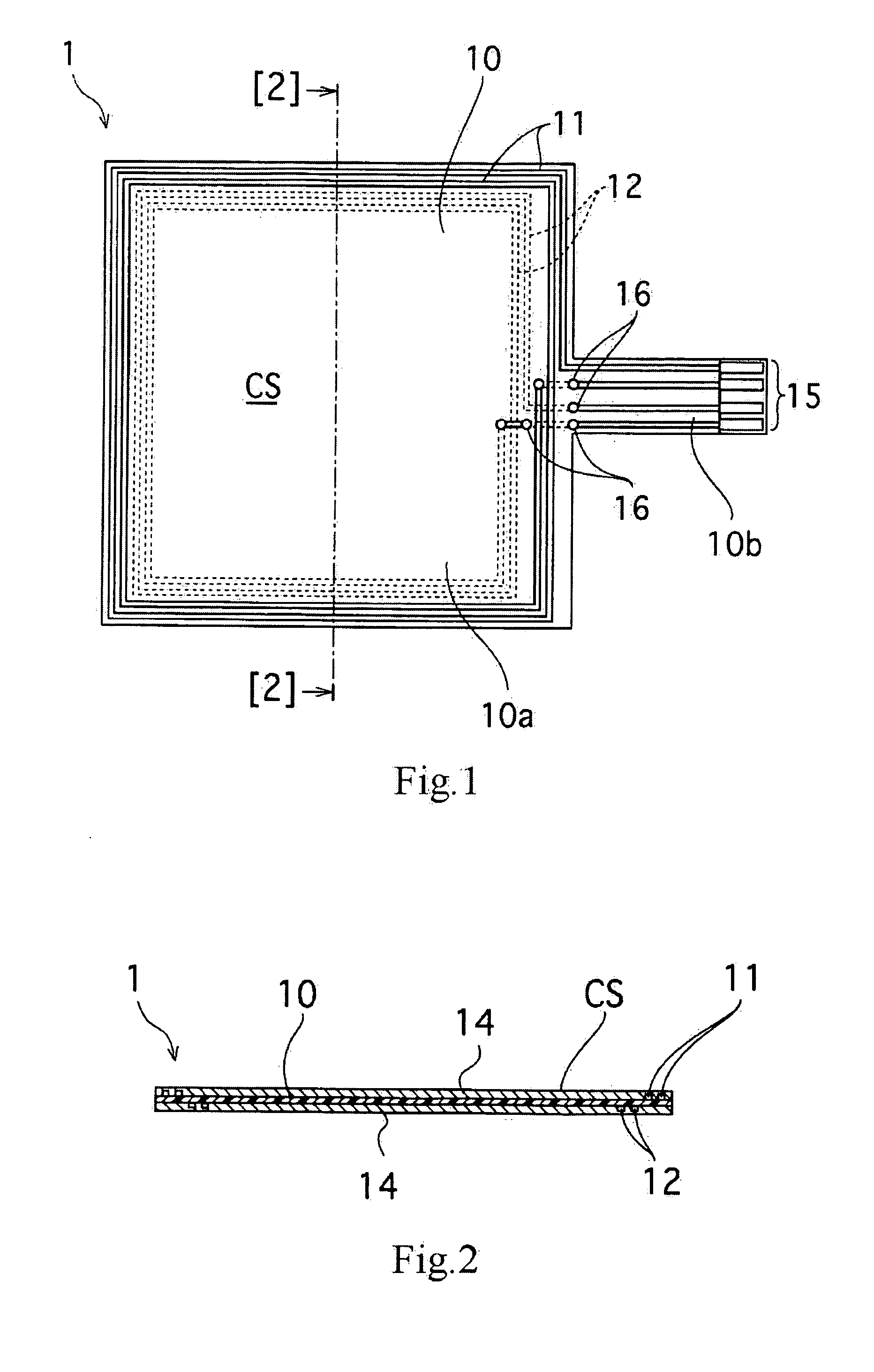
[0040]FIGS. 1 and 2 illustrate an antenna module 1 according to a first embodiment of the present invention. Specifically, FIG. 1 is a plan view of the antenna module 1, and FIG. 2 is a cross-sectional view taken along line [2]-[2] in FIG. 1.

[0041] The antenna module 1 according to the first embodiment includes a common base substrate 10 on which a first antenna coil 11 for communication with a reader / writer and a second antenna coil 12 for communication with an IC tag are disposed.

[0042] The second antenna coil 12 indicated by a dashed line in the drawing is disposed on the bottom surface (underside of the drawing) of the base substrate 10. This will be described in detail below.

[0043] The base substrate 10 is composed of an insulating material. The base substrate 10 may be formed of a material having rigidity (self-supporting capability), such as a glass epoxy substrate, or may be formed of a flexible material, such as polyimide, PET, and PEN.

[0044] The base substrate 10 inclu...

second embodiment

[0077]FIGS. 10 and 11 illustrate an antenna module 2 according to a second embodiment of the present invention. The components in the drawings that are equivalent to those in the first embodiment are indicated by the same reference numerals, and detailed descriptions of those components will therefore be omitted.

[0078]FIG. 10 is a plan view of the antenna module 2, and FIG. 11 is a cross-sectional view taken along line [11]-[11] in FIG. 10.

[0079] The antenna module 2 according to the second embodiment has the base substrate 10 on which the first antenna coil 11 for communication with a reader / writer, the second antenna coil 12 for communication with an IC tag, and an RFID circuit 30 are disposed. The RFID circuit 30 includes the IC chip 24 storing data to be transmitted via the first and second antenna coils.

[0080] The RFID circuit 30 corresponds to a “signal processing circuit” according to the present invention. In addition to the IC chip 24, the RFID circuit 30 includes a set ...


PUM


Abstract

An antenna module and a portable communication terminal equipped with the antenna module are provided. The antenna module has a space-saving design, and also has both a capability for long communication distance for a tag function and a capability for wide communication range for a reader/writer function.
A first antenna coil (11) for communication with a reader/writer and a second antenna coil (12) for communication with an IC tag are disposed on a base substrate (10). The first antenna coil (11) is disposed in an outermost periphery section of the base substrate (10) so that a communication distance is attained. The second antenna coil (12) is disposed within an inner periphery of the first antenna coil (11) so as to achieve overall size reduction of the module.

Description

TECHNICAL FIELD [0001] The present invention relates to an antenna module used for an RFID (radio frequency identification) system, and to a portable communication terminal equipped with such an antenna module. BACKGROUND ART [0002] Conventionally, in RFID technology typically known for a contact-free IC card system, an antenna coil is built in an identification IC tag, such as an IC card, and forms inductive coupling with an electric wave released from a transmitter-receiver antenna of a reader / writer, such that data communication is performed. [0003] Currently, a mode for performing data communication between an IC tag and a reader / writer is applied to, for example, making payments for train fares using an IC card. In such an example, when checking the usage of an IC card, a ticket-vending machine set in a train station or a specific viewer for reading data in the IC card is necessary. Moreover, in order to bill the IC card, the IC card must be billed (by cyber billing) on the Int...

Claims


Application Information

Patent Timeline
IPC IPC(8): G06K7/08G06K19/06B42D15/10G06K17/00G06K19/07G06K19/077H01Q1/22H01Q1/24H01Q1/38H01Q1/52H01Q7/00H01Q21/28H04B1/59H04B5/02
CPCG06K7/10336H01Q1/22H01Q1/2216H01Q1/2225H01Q1/242H01Q7/00G06K19/00H01Q1/24H01Q21/28
Inventor TAKAHASHI, ISAOAKIHO, HIRAKU
Owner SONY CORP
Why Eureka
Try Eureka