Bronchoscopic lung volume reduction valve

a technology of lung volume and bronchial valve, which is applied in the direction of blood vessels, prostheses, drug compositions, etc., can solve the problems of emphysema patients' difficulty in breathing, damage to the walls of tiny air spaces, and obstructing airways, so as to achieve the effect of allowing mucus to flow

Active Publication Date: 2007-05-03
BOSTON SCI SCIMED INC
View PDF3 Cites 98 Cited by
  • Summary
  • Abstract
  • Description
  • Claims
  • Application Information

AI Technical Summary

Benefits of technology

[0003] In one aspect, the present invention is directed to a valve to perform lung volume reduction procedures, which comprises a braided structure adapted for endoscopic insertion in a bronchial passage, the braided structure having a proximal end and a distal end, a non porous coating adapted to prevent flow of air through the braided structure, a constricted portion of the braided structure preventing flow of air through a tubular central lumen of said braided structure, and defining a funnel shaped portion thereof, and at least one hole of the braided structure adapted to permit flow of mucus from the distal end to the proximal end. The funnel shaped portion is adapted to prevent flow of air from the proximal end to the distal end.

Problems solved by technology

Patients affected with emphysema have a difficult time breathing.
When the bronchi become irritated, some of the airways may be obstructed, trapping air in the lung beyond them.
The walls of the tiny air spaces may become damaged and may tear.
If the stretching and destruction of the walls of the alveoli continues, portions of the lungs may become enlarged, at the same time becoming less efficient in exchanging oxygen for carbon dioxide.
However, LVRS is a major surgical procedure with complications and potential morbidity and mortality, and is not suited for patients that may be weak, or otherwise unable to undertake major surgery.

Method used


Image

  • Bronchoscopic lung volume reduction valve
  • Bronchoscopic lung volume reduction valve
  • Bronchoscopic lung volume reduction valve

Examples


Embodiment Construction

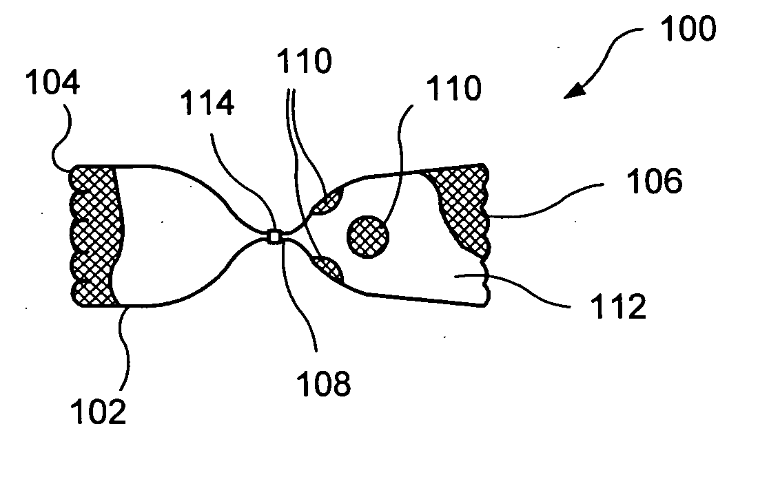
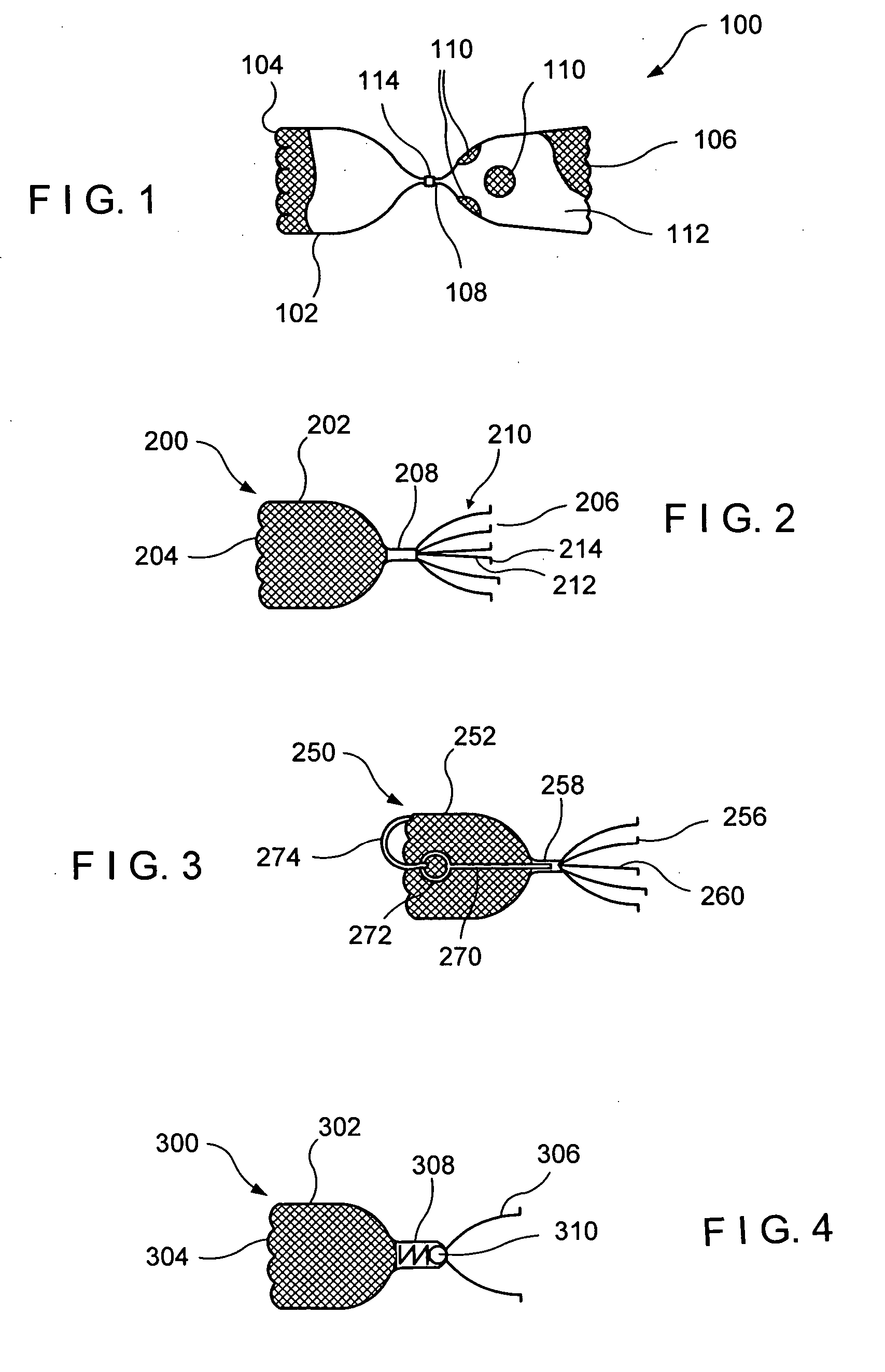
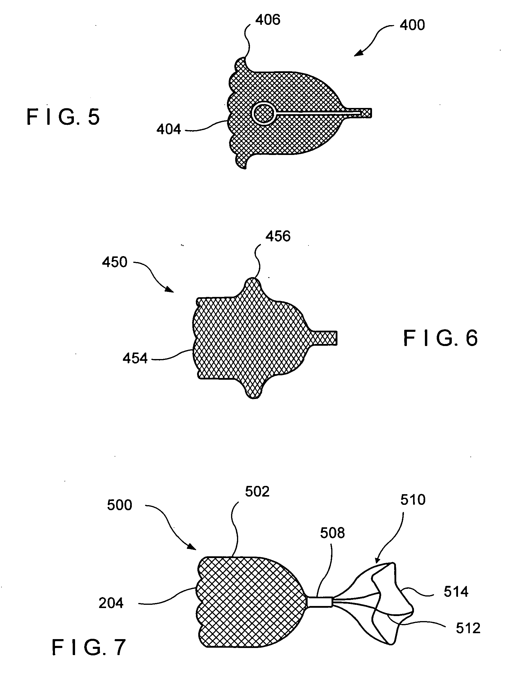
[0012] The present invention may be further understood with reference to the following description and the appended drawings, wherein like elements are referred to with the same reference numerals. The present invention is related to medical devices used to provide unidirectional flow within biological flow passages. More specifically, the invention is related to medical devices used to control the flow of air and of mucus within the bronchial passages of a lung.

[0013] The exemplary embodiments of the present invention described herein relate to a one way valve which can be used to control the flow of a gas through a biological flow passage. In one example, the one way valve is used during lung volume reduction procedures which are often performed to alleviate the symptoms of emphysema. The one way valve may be used to restrict the flow of air reaching selected portions of the lungs, and at the same time to permit the flow of residual air and / or mucus and other fluids out of the lu...


PUM


Abstract

A valve to perform lung volume reduction procedures is described. The valve is formed of a braided structure that is adapted for endoscopic insertion in a bronchial passage of a patient's lung. The braided structure has a proximal end and a distal end and is covered with a non porous coating adapted to prevent flow of air into the. A constricted portion of the braided structure is used to prevent flow of air through a central lumen of the structure, and to define at least one funnel shaped portion. The funnel shaped portion blocks the flow of air towards the constriction, i.e. towards the core of the lung. At least one hole is formed in the braided structure to permit flow of mucus from the distal end to the proximal end, to be expelled out of the lungs.

Description

BACKGROUND [0001] Emphysema is a chronic, progressive disease of the lungs which affects millions of Americans. Patients affected with emphysema have a difficult time breathing. Emphysema is not presently curable, but it can be treated. Emphysema often is a result of chronic infection or irritation of the bronchial tubes. The bronchial tubes extend from the windpipe to the lungs, and look like branches of a tree, with the branches becoming smaller and smaller until each one ends in a cluster of small air spaces in the lung, called alveoli. When the bronchi become irritated, some of the airways may be obstructed, trapping air in the lung beyond them. The walls of the tiny air spaces may become damaged and may tear. If the stretching and destruction of the walls of the alveoli continues, portions of the lungs may become enlarged, at the same time becoming less efficient in exchanging oxygen for carbon dioxide. Healthy portions of the lungs may be compressed by the diseased lung portio...

Claims


Application Information

Patent Timeline
Patent Type & Authority Applications(United States)
IPC IPC(8): F16K51/00A61F2/04A61F2/90
CPCA61B17/12022A61F2230/008A61B17/12172A61B2017/00575A61B2017/00592A61B2017/00597A61B2017/00606A61B2017/00615A61B2017/00619A61F2/07A61F2/24A61F2/90A61F2002/043A61F2250/0039A61M39/22A61M2210/1039A61F2220/0008A61F2230/0078A61B17/12104A61F2210/0014A61F2210/0057A61F2250/001A61P11/00A61F2/2476A61F2/04A61F2/82A61M2039/244A61M2039/248F16K15/00F16K99/0003F16K2099/0088
Inventor CLERC, CLAUDE
Owner BOSTON SCI SCIMED INC
Why Eureka
Try Eureka