
Seat pad

a seat pad and seat technology, applied in the field of seat pads, can solve the problems of not providing a means, designs folded with a fabric backing may be reversible but not stable, and the type of non-attached gripping surfaces could become a safety hazard,

Inactive Publication Date: 2007-05-03
CONFORTI CARL J
View PDF5 Cites 25 Cited by
  • Summary
  • Abstract
  • Description
  • Claims
  • Application Information

AI Technical Summary

Benefits of technology

[0005] In accordance with the present invention, an integrated seat pad assembly is provided. The assembly includes an affixed gripping member that forms a pocket and prevents the pad from sliding during use. The gripping member is secured along its edge to the seat pad forming a pocket thereon. The gripping member is rotatably reversible, and attached to the seat pad assembly held in close proximity of either side of the seat pad surface area allowing for alternative sides of the seat pad to be selectively chosen, thereby exposing alternative sides for cleanliness, variations in materials or fashion designs.
[0006] The seat pad construction ensures that movement is substantially eliminated between the gripping member and seating surface when weight is applied to the pad seating surface. The pad offers an improved, secure, means providing a non slip seating surface without the use of strings, ties or other fastening means. The construction of the multi-use pad is manufactured at a low cost minimizing the expense of materials, separate fasteners and attaching mechanisms.
[0007] The pad gripping component is resiliently reversible, and fixedly attached to at least a portion of the outer perimeter of the pad assembly and preferably at least two sides or points between the top and bottom surfaces of the seat pad assembly. The pad gripping component may also be fixedly attached to at least a portion of three sides of the approximate midsection of the side panel in a square or rectangular shape body. The gripping component securely fastened to a portion about the perimeter of the pad assembly forms a pocket on at least one panel of the seat pad assembly offering an added feature of a convenient storage. For cost savings in manufacturing, the seat pad uses only a portion of the gripping component anti-slip material as compared to the prior art. The pad gripping component can be selectively placed to secure the seat pad from movement, at a minimum approximately one quarter to one half of the surface pad area that contacts the seating surface or structure.

Problems solved by technology

These types of non-attached gripping surfaces could become a safety hazard due to the likelihood of separation from the pad.
These designs folded with a fabric backing may be reversible but not stable without additional fasteners or fixtures to prevent shifting or rotating movement when weight is applied.
The seat cover can be folded at a mid plane to provide a means to overlay the fabric portion, but the overlay of two layers do not provide a means to resist slippage between the two layers, and are often big and bulky to store and to handle.
Some pads found constructed of polyvinyl chloride material may offer some slip resistance, but not always adequate in gripping mating surfaces, limiting in material selection.
A disadvantage of the above chair cushions with permanently attached gripping surfaces is that only one side of the cushion can be exposed during use.
If the exposed side becomes irreparably damaged or stained, then it may require replacement because the cushion cannot be reversed.
If the gripping member was permanently attached the chair pad would be somewhat bulky and cumbersome to handle, and it also should be noted the seat pad and gripping member may not provide sufficient gripping support if twisting or torque is applied to the seating surface, having only one side or panel attached to the gripping member.
One disadvantage of the above disclosed seat cushion is the seat pad and gripping surface are not securely attached to prevent movement between the pad and seating surface and does not offer an economical means to fabricate the seat pad.

Method used


Image

  • Seat pad
  • Seat pad
  • Seat pad

Examples


Embodiment Construction

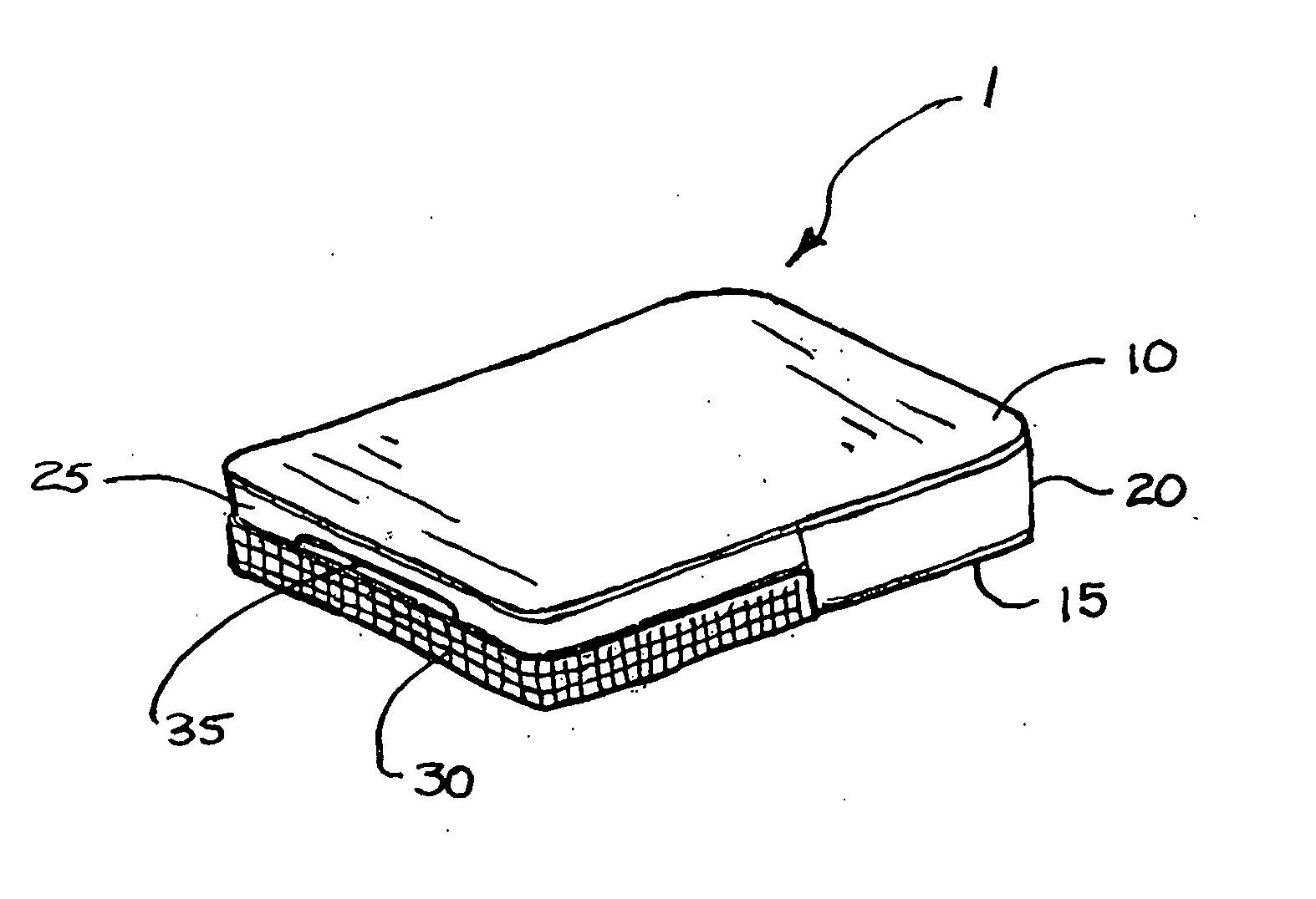
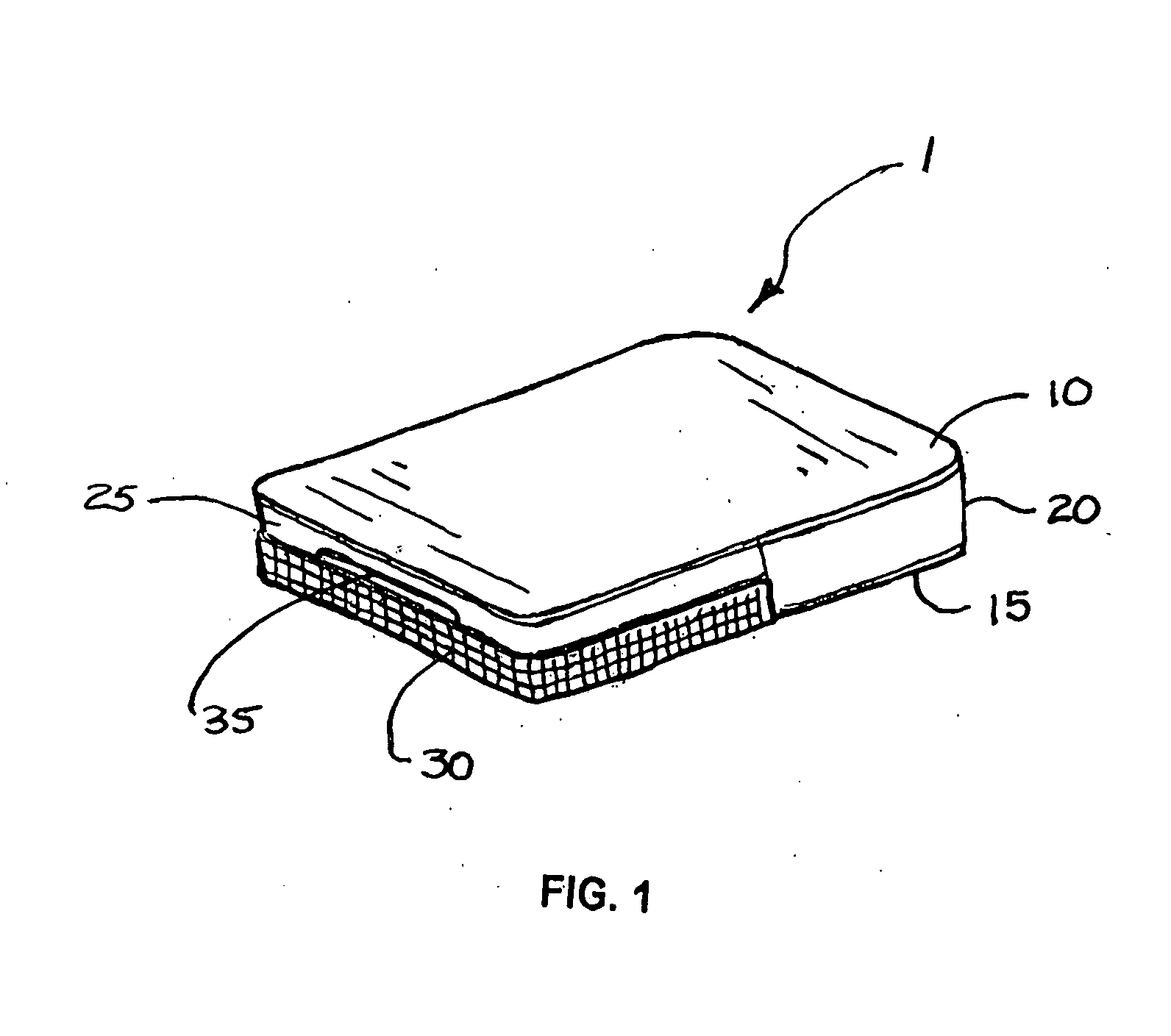
[0030] While the invention described is susceptible of embodiment in many different forms, they are shown in the drawing, specification and herein described in the detailed specific embodiments and is not intended to be limited to the specific embodiments illustrated. Referring to FIG. 1 the seat pad 1 of the present invention is constructed of a first upper panel 10, and a second lower panel 15 comprising a semi-rigid or resilient fabric like material. The first upper panel 10, and second lower panel 15 may provide different materials, colors, textures or a design that may be provided by other conventional methods. A third side panel component 20 is provided between the first upper panel 10, and second lower panel 15 to be attached at least a portion of the outer perimeter of upper panel 10, and lower panel 15. The third side panel 20 may be fixedly attached to the upper panel 10, and lower panel 15, to at least a portion of the outer periphery to form a three dimensional shape. An...


PUM


Abstract

An improved seat pad and integrated gripping member is provided, which prevents the pad from slipping when placed between a seating surface and individual. The gripping member is permanently attached to the seat pad along its edge and covers a portion of either side of the seating surface. The gripping member is reversible therefore either side of the seat pad may be selectively exposed during use. This allows both seat pad sides to be constructed of different materials, colors, or patterns and be interchangeable when desired by the user.

Description

FIELD OF THE INVENTION [0001] The invention pertains to seat pads, and more particularly to seat pad assemblies that are constructed of a cushion, a non slip member and providing a multi functional, decorative, protective cover assembly for an individual to sit comfortably and securely on an adjoining surface or structure. BACKGROUND OF THE INVENTION [0002] Many pads exist in the market today that have various shapes, sizes and fashion designs. Seat pads are sold in the market constructed mostly of a fabric like material, and it is not uncommon to find these materials made of synthetic, natural fibers or other man made materials. Filler materials such as foam or other like materials are used to create cushioning comfort in the pad. Pads are typically constructed to provide the same cushioning comfort when the pad is rotated from one side to the other. Chair pads, seat pads, decorative pillows and cushions (hereafter “pads”) are examples of articles that may be placed over a smooth s...

Claims


Application Information

Patent Timeline
IPC IPC(8): A47C27/00
CPCA47C7/62A47C31/126A47C7/021
Inventor CONFORTI, CARL J.
Owner CONFORTI CARL J
Learn More