Regulator with load tracking bias

a load tracking and voltage regulator technology, applied in the field of electric circuits, can solve the problems of wide input voltage range and difficulty in satisfying all three tradeoffs at the same time, and achieve the effect of high (good) power supply rejection ratio

Inactive Publication Date: 2007-05-03
IBM CORP
View PDF17 Cites 9 Cited by
  • Summary
  • Abstract
  • Description
  • Claims
  • Application Information

AI Technical Summary

Benefits of technology

[0008] Disclosed is an electrical circuit that provides accurate, regulated output voltage over a wide range of input voltages, while exhibiting each of three desired characteristics: accuracy across different supply / process / temperature; stability and linearity yielding phase / gain margins; and high (good) power supply rejection ratio (PSRR). The circuit comprises an output node having a load current and an amplifier having a first input coupled to a reference voltage and receiving a bias input current that is a pre-established proportionate size of the load current across the output node, such that a change in the load current results in a proportionate change in the bias input current. The electrical circuit represents a voltage regulator that provides accurate, linear output voltage that is a predictable portion of the reference voltage.

Problems solved by technology

With conventional voltage regulator circuits, it is difficult to satisfy all three tradeoffs simultaneously, particularly over a wide input voltage range.

Method used


Image

  • Regulator with load tracking bias
  • Regulator with load tracking bias
  • Regulator with load tracking bias

Examples


Embodiment Construction

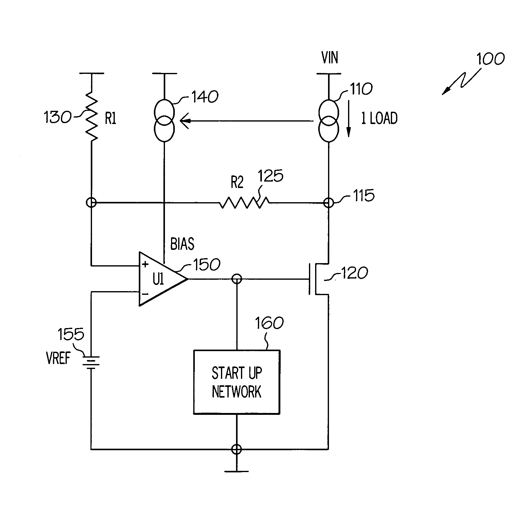
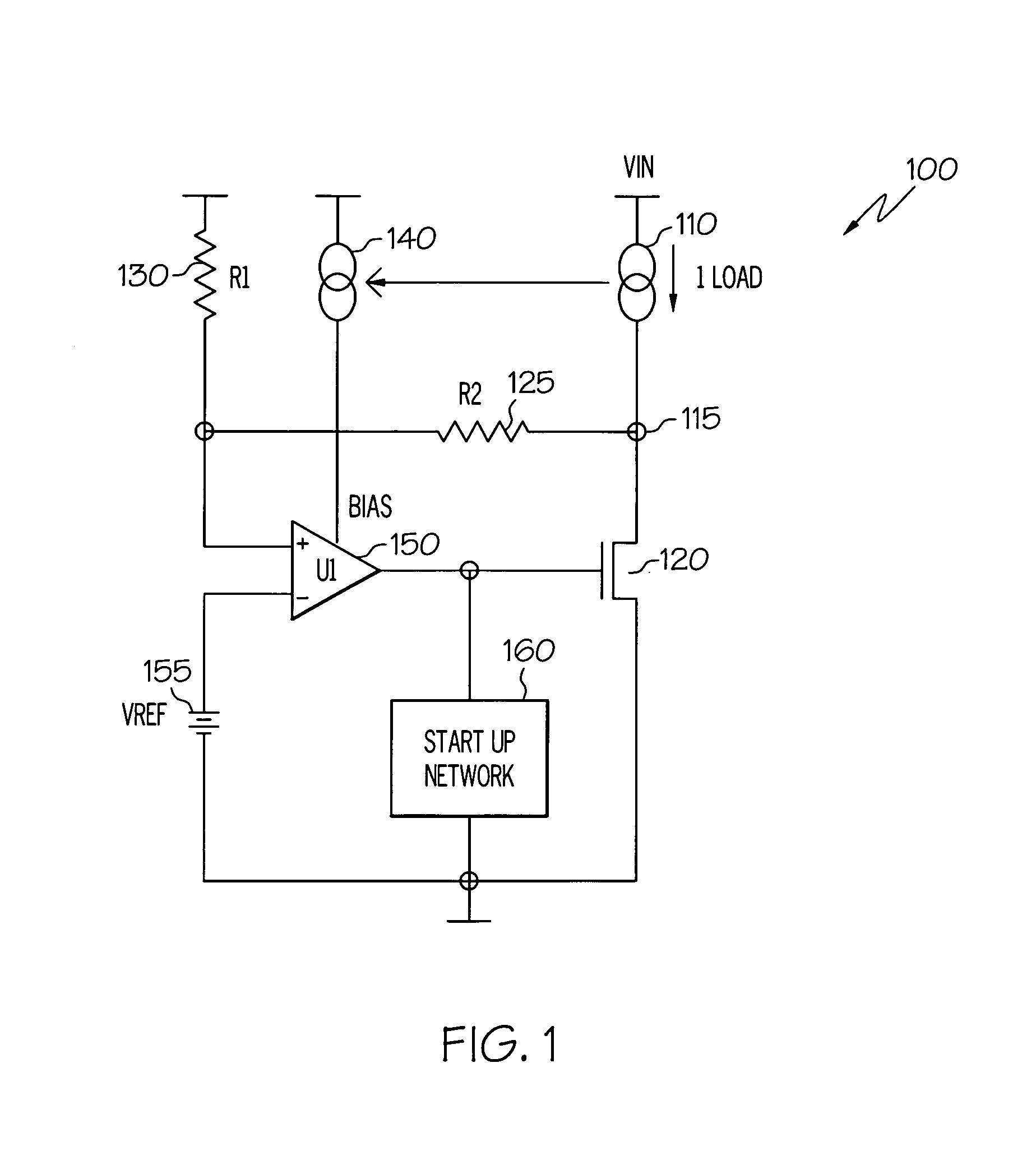
[0014] The present invention provides an electrical circuit that provides accurate, regulated output voltage over a wide range of input voltages, while exhibiting each of three desired characteristics: accuracy across different supply / process / temperature; unconditional stability yielding acceptable phase / gain margins; and high power supply rejection ratio (PSRR). The circuit comprises an output node having a load current and an amplifier having a first input coupled to a reference voltage and receiving a bias input current that is a pre-established proportionate size of the load current across the output node, such that a change in the load current results in a proportionate change in the bias input current. In one embodiment, the output of the amplifier is coupled to the gate of a transistor, which is coupled to the output node in parallel with a pair of series-connected input resistors. The electrical circuit represents a voltage regulator that provides accurate, linear output vol...


PUM


Abstract

An electrical circuit that provides accurate, regulated output voltage over a wide range of input voltages, while exhibiting each of three desired characteristics: accuracy across different supply / process / temperature; stability and linearity yielding phase / gain margins; and high (good) power supply rejection ratio (PSRR). The circuit comprises an output node having a load current and an amplifier having a first input coupled to a reference voltage and receiving a bias input current that is a pre-established proportionate size of the load current across the output node, such that a change in the load current results in a proportionate change in the bias input current. The electrical circuit represents a voltage regulator that provides accurate, linear output voltage that is a predictable portion of the reference voltage.

Description

BACKGROUND OF THE INVENTION [0001] 1. Technical Field [0002] The present invention relates generally to electrical circuit and in particular to voltage regulators and designs thereof. [0003] 2. Description of the Related Art [0004] Conventionally, output impedance and thus output voltage of load regulator devices fluctuate due to one or more of a plurality of factors, including changes in temperature or other operating environmental conditions, and / or changes in current, etc. experienced by the circuit. Voltage (or load) regulation, which measures and counters variations in regulator output voltage due to changes in loading is conventionally dependent on output impedance. Those skilled in the art of electrical circuits and circuit design appreciate the need / desire for accurate, linear output characteristics of load / voltage regulator circuits / devices. [0005] In integrated circuit (IC) chip design, for example, the circuit devices that make up the IC chip typically require a pre-set a...

Claims


Application Information

Patent Timeline
Patent Type & Authority Applications(United States)
IPC IPC(8): G05F1/00
CPCG05F1/575Y10S323/901
Inventor RASMUS, TODD MORGAN
Owner IBM CORP
Why Eureka
Try Eureka